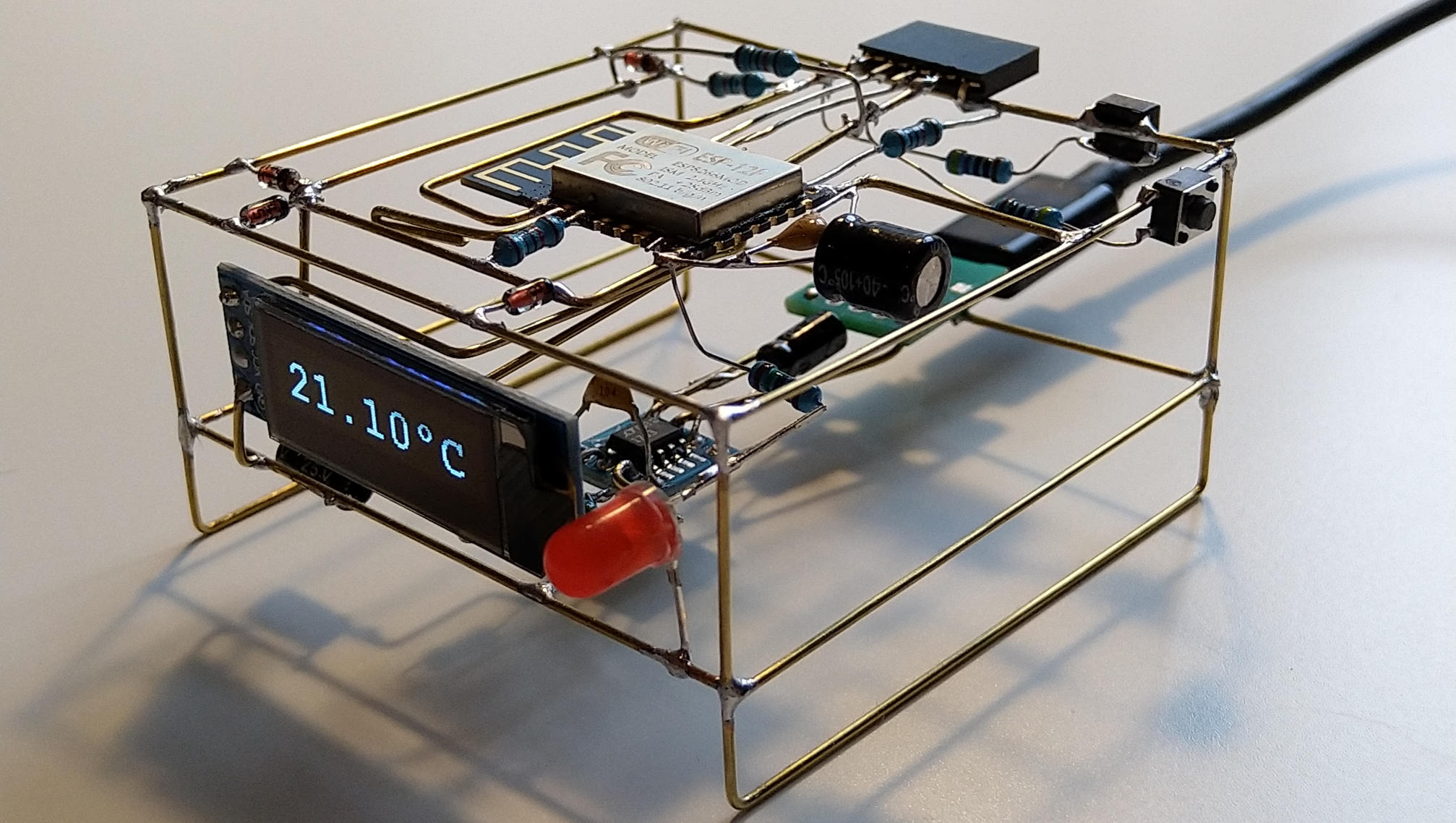
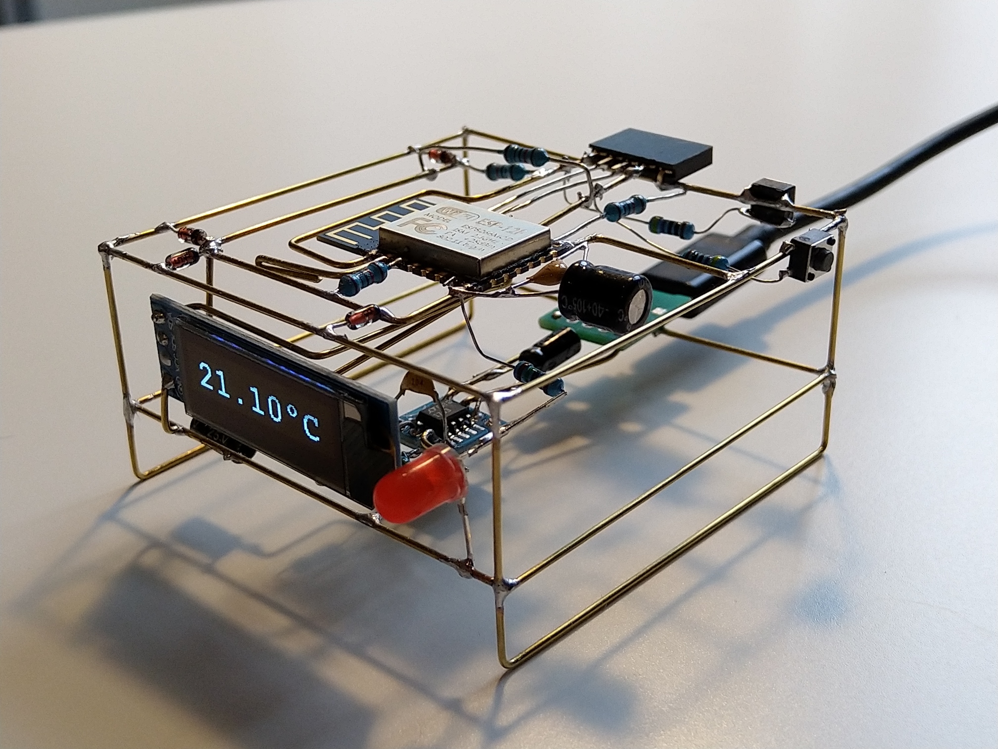
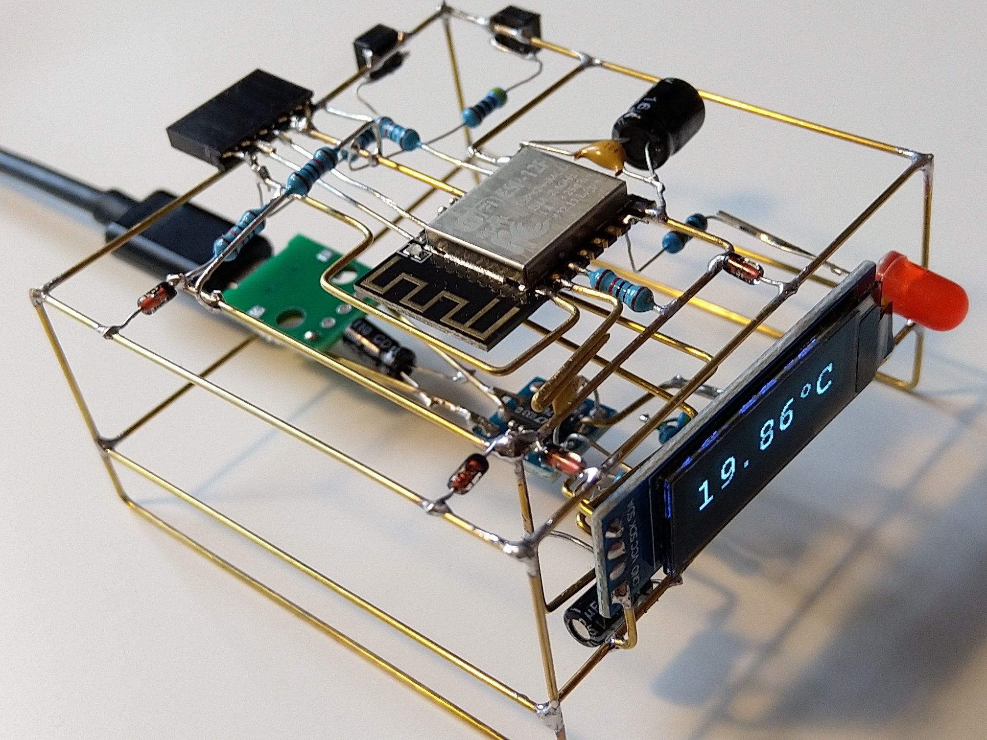
My second freeform creation, or third if we include The CyborgDuck is here. I wanted to do something simple in order to gather more experience and improve my skills.
This article is Part 1 in a 3-Part Series.
- Part 1 -Freeform ESP8266 OLED MQTT client
- Part 2 -ESP8266 based room-conditions monitor, Part 1
- Part 3 -ESP8266 based room-conditions monitor, part 2: PCB
Circuit
When I was thinking what to build as a next, simple free-form circuit, my eyes fell on my RoomMonitor project (link is to a GitHub repository with its firmware). That’s one of my long-running projects. Basically, a bunch of sensors connected to ESP8266, battery powered, measures conditions in a room and sends data to some online service via MQTT. Nothing that much interesting. The challenge here is to make it last as long as possible on a battery. It might evolve into a weather station in the future. Right now, I am running the second prototype and planning the third one. Then, maybe, I might think about making some final form for that.
But since this is a battery-powered device and the micro-controller sleeps most of the time, there’s no display. I have always planned to make another device which would act as a remote display of sorts.
The idea is simple:
- Use ESP8266 again, I have plenty of them and know them well enough.
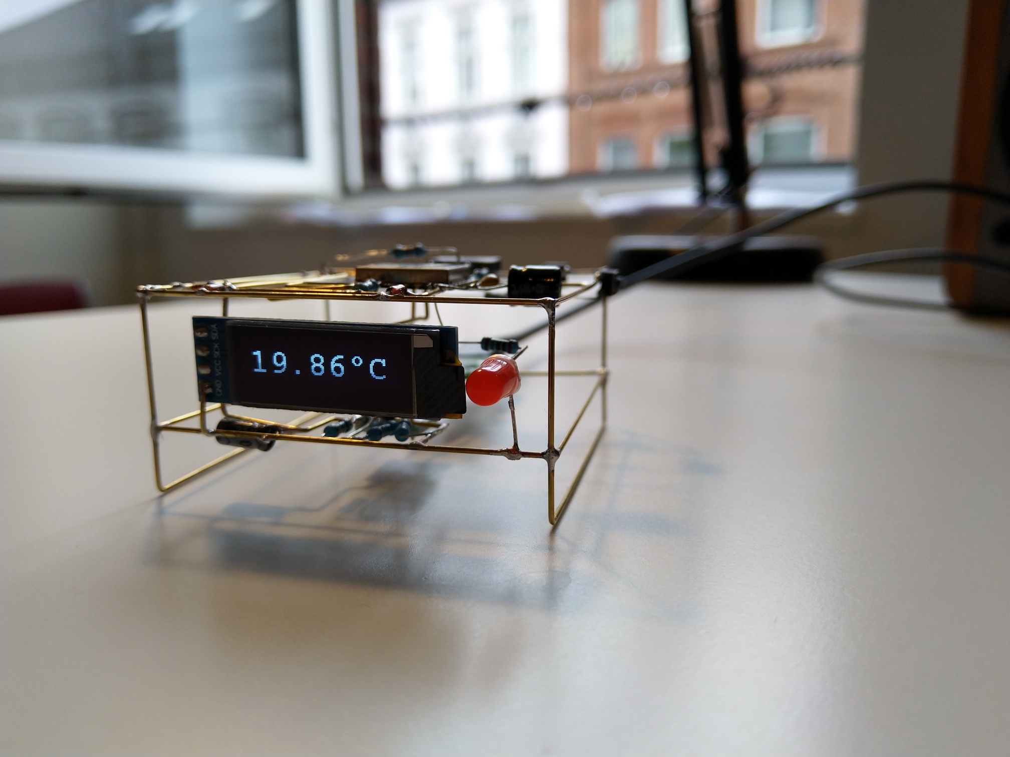
- Use a small OLED display and show only one value (temperature).
- Powered through a USB connector, since I have plenty of USB power sources. But that also means I need to step-down the voltage from 5V to ~3.3V
- Include LED which would indicate low battery voltage on the RoomMonitor device.
- Have some touch-like input which would allow to cycle values on a display or similar.
- Have a way how to program the ESP8266. For the firs firmware upload and for emergencies, when over the air update fails. Normally OTA should be used since it’s easier than connecting FTDI every time.
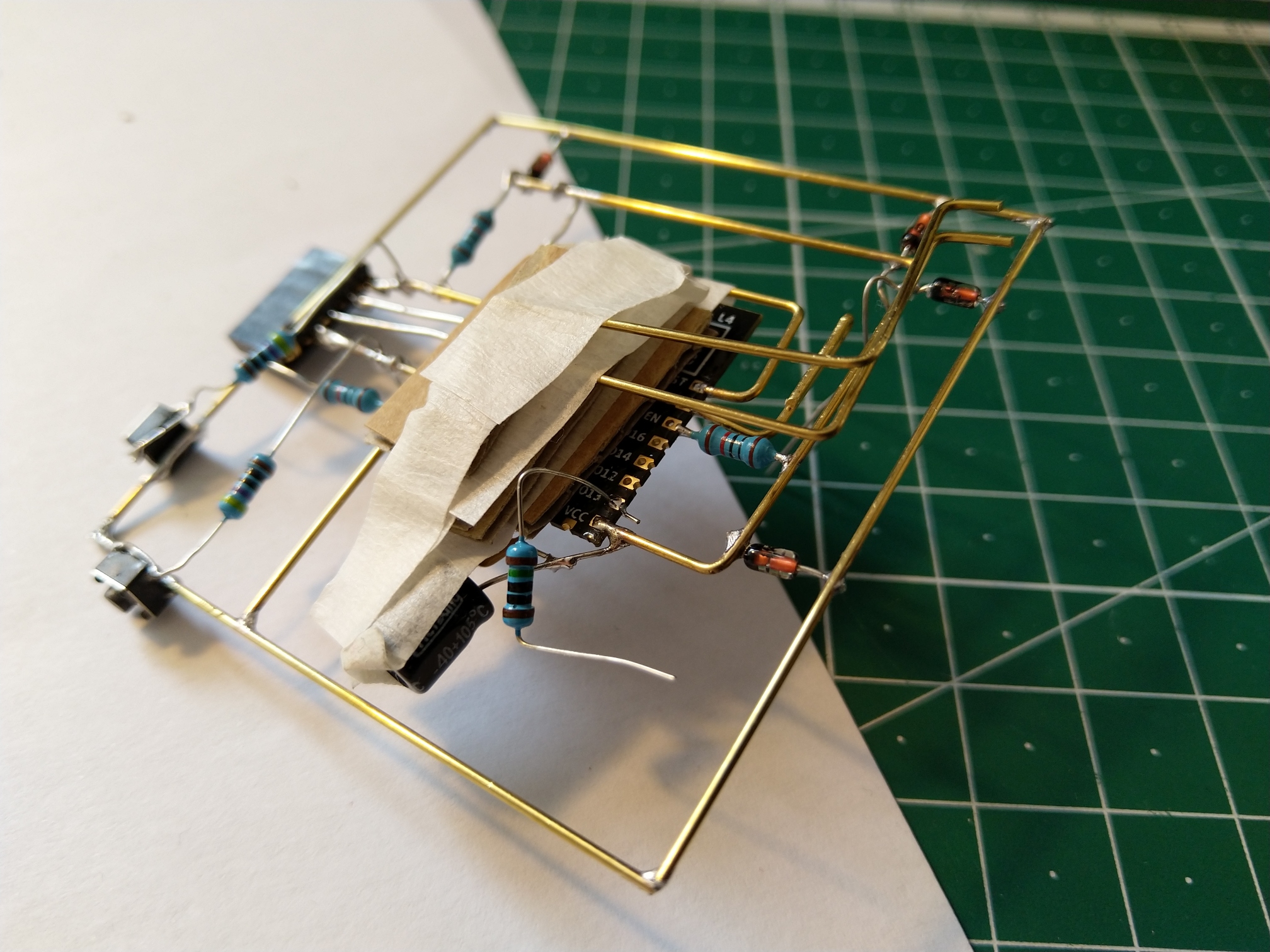
Since I am very new to free-form, I wanted to have the construction as simple as possible. Therefore, I decided to:
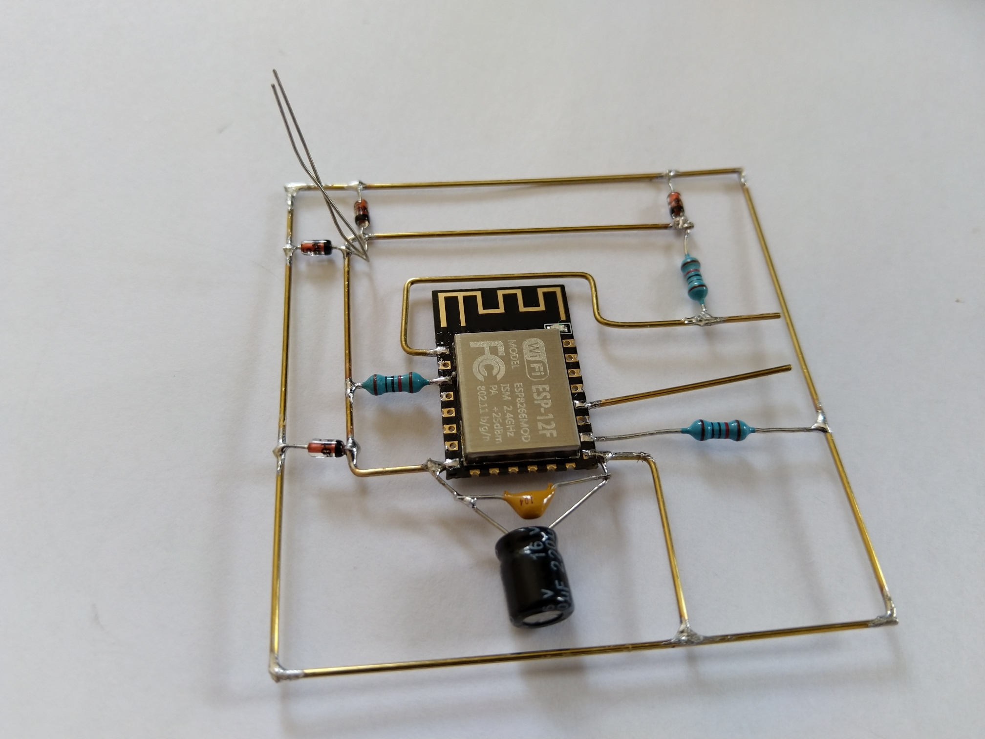
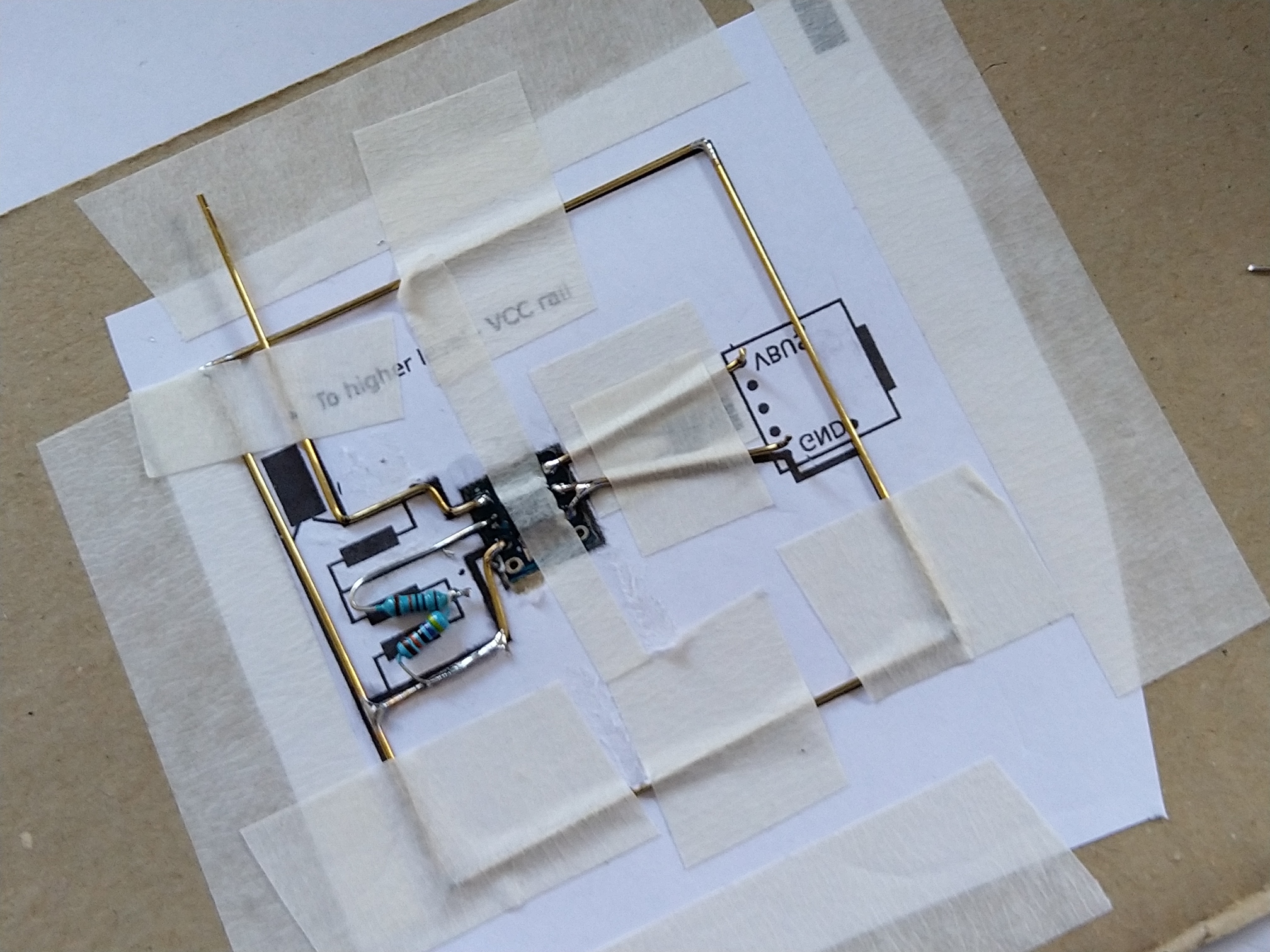
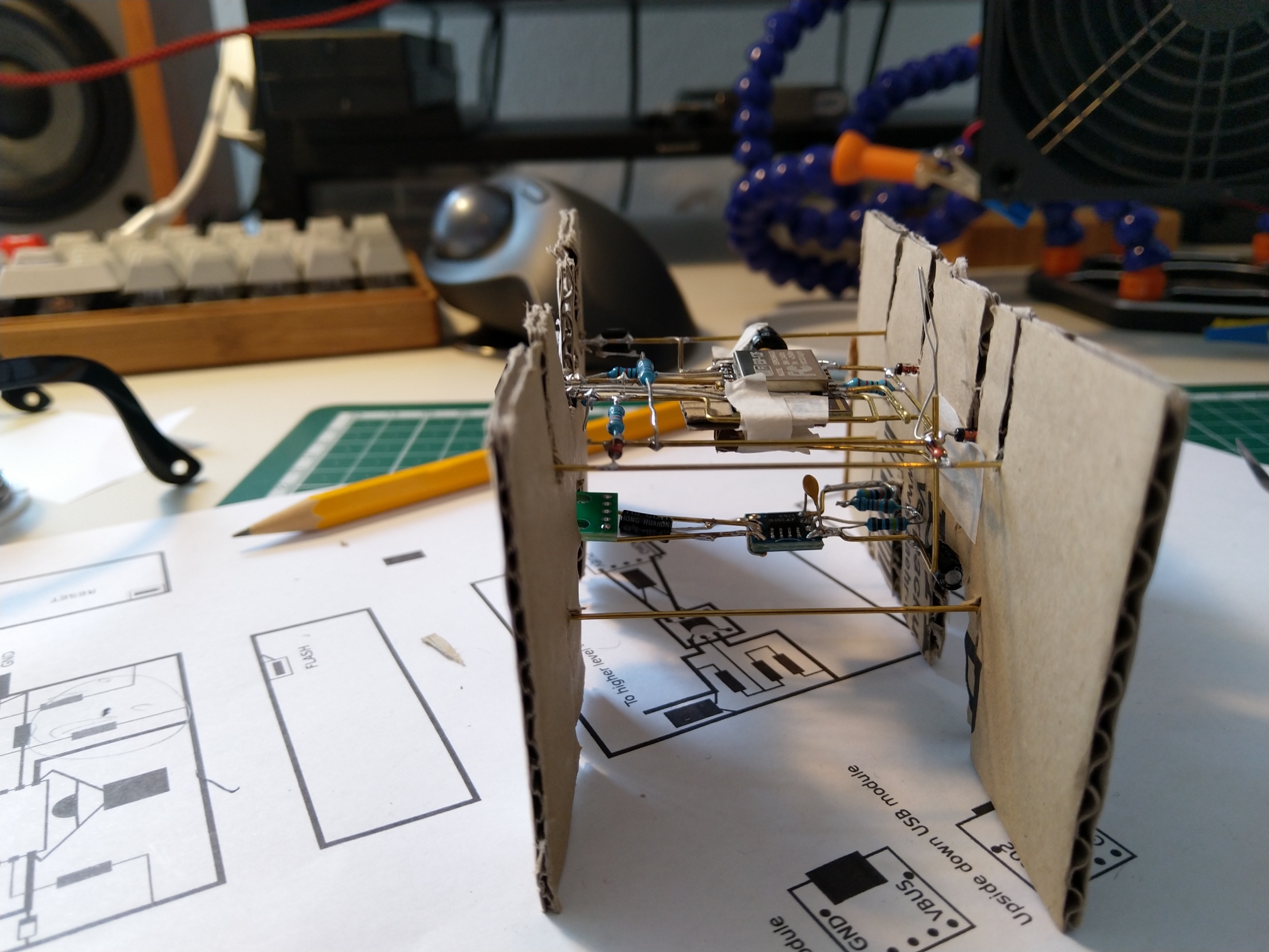
- try to do most of the circuit in flat layers which would be easier to solder together,
- use simple shape - cube or cuboid,
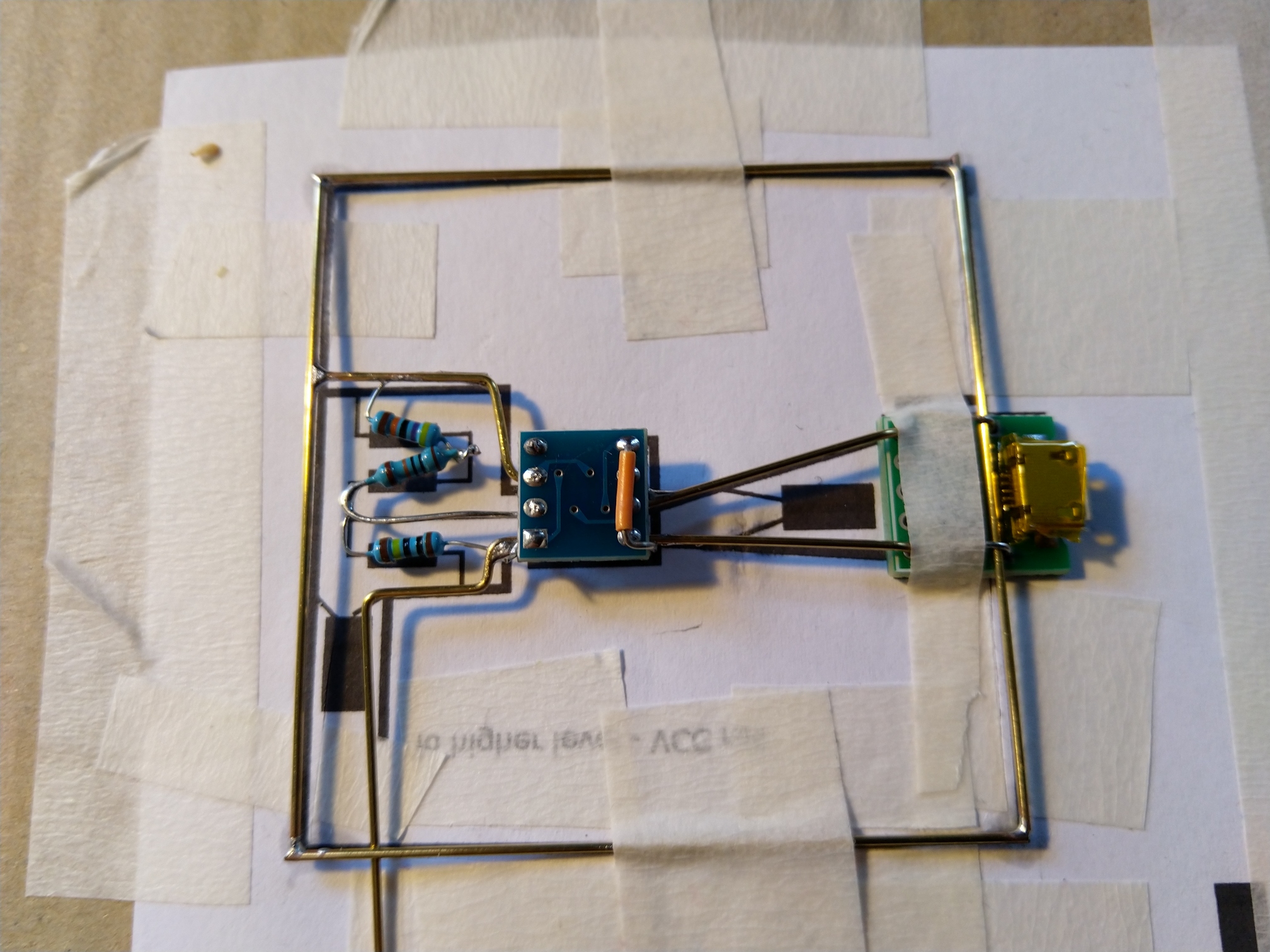
- use PCB breakouts for some things - OLED display module, USB connector, and LDO.
Here’s a schematic for the final circuit (available also on EasyEDA).
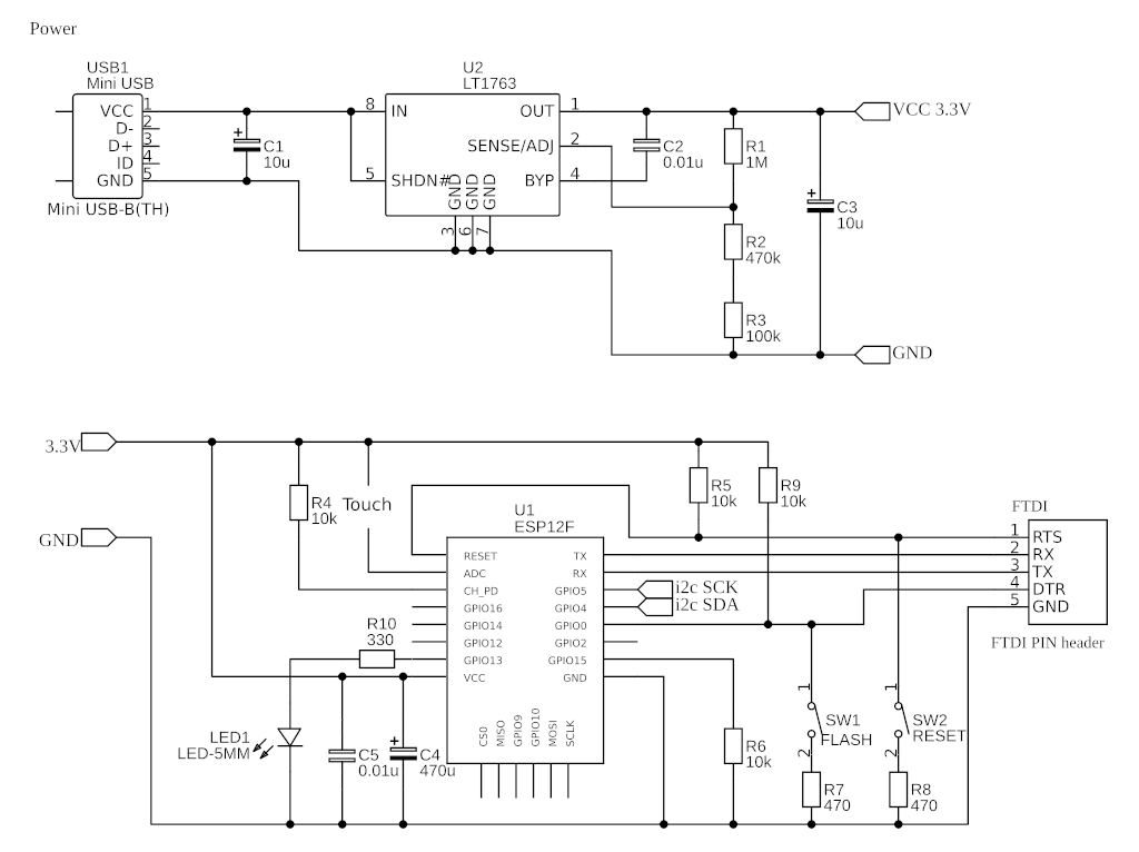
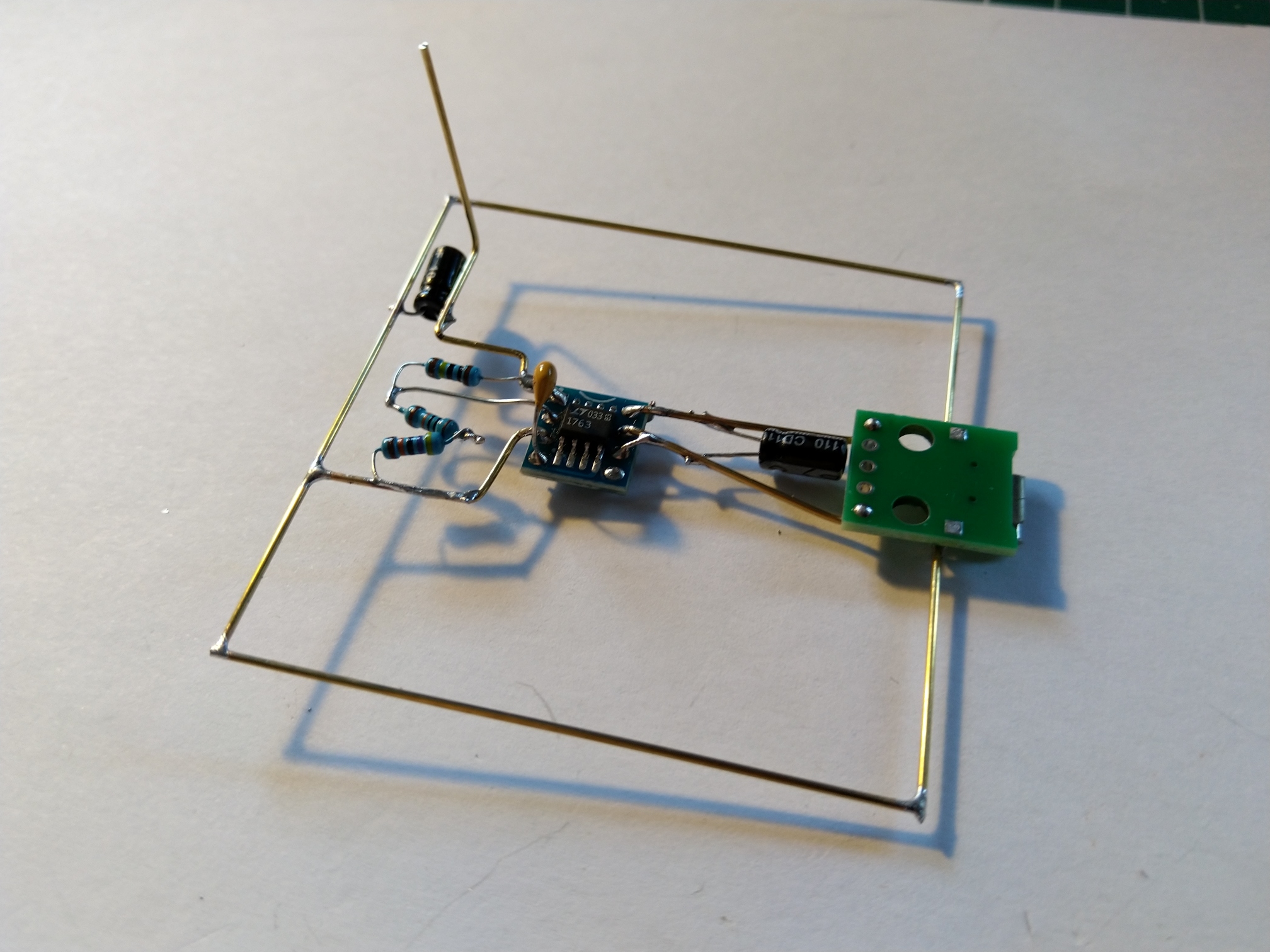
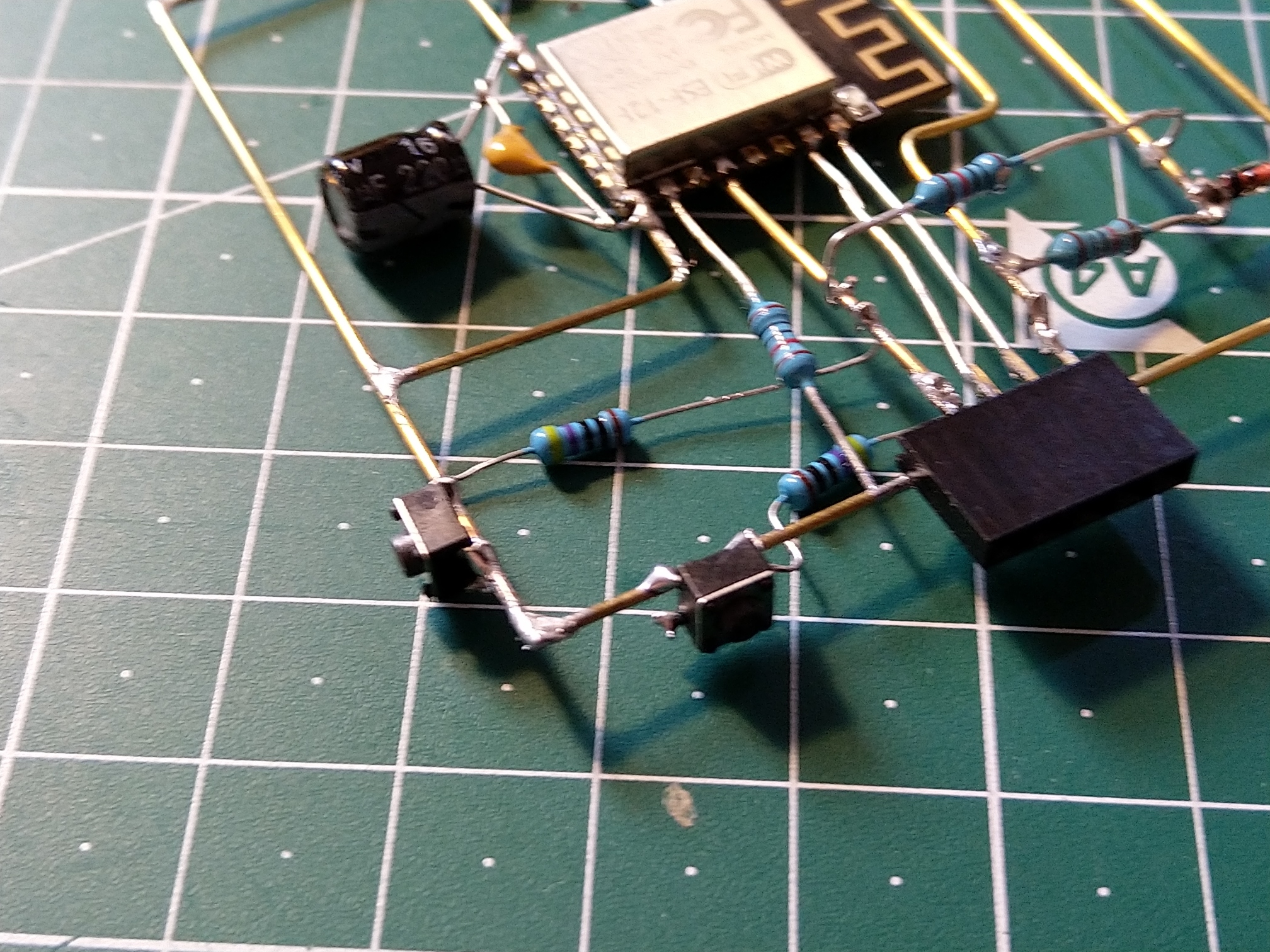
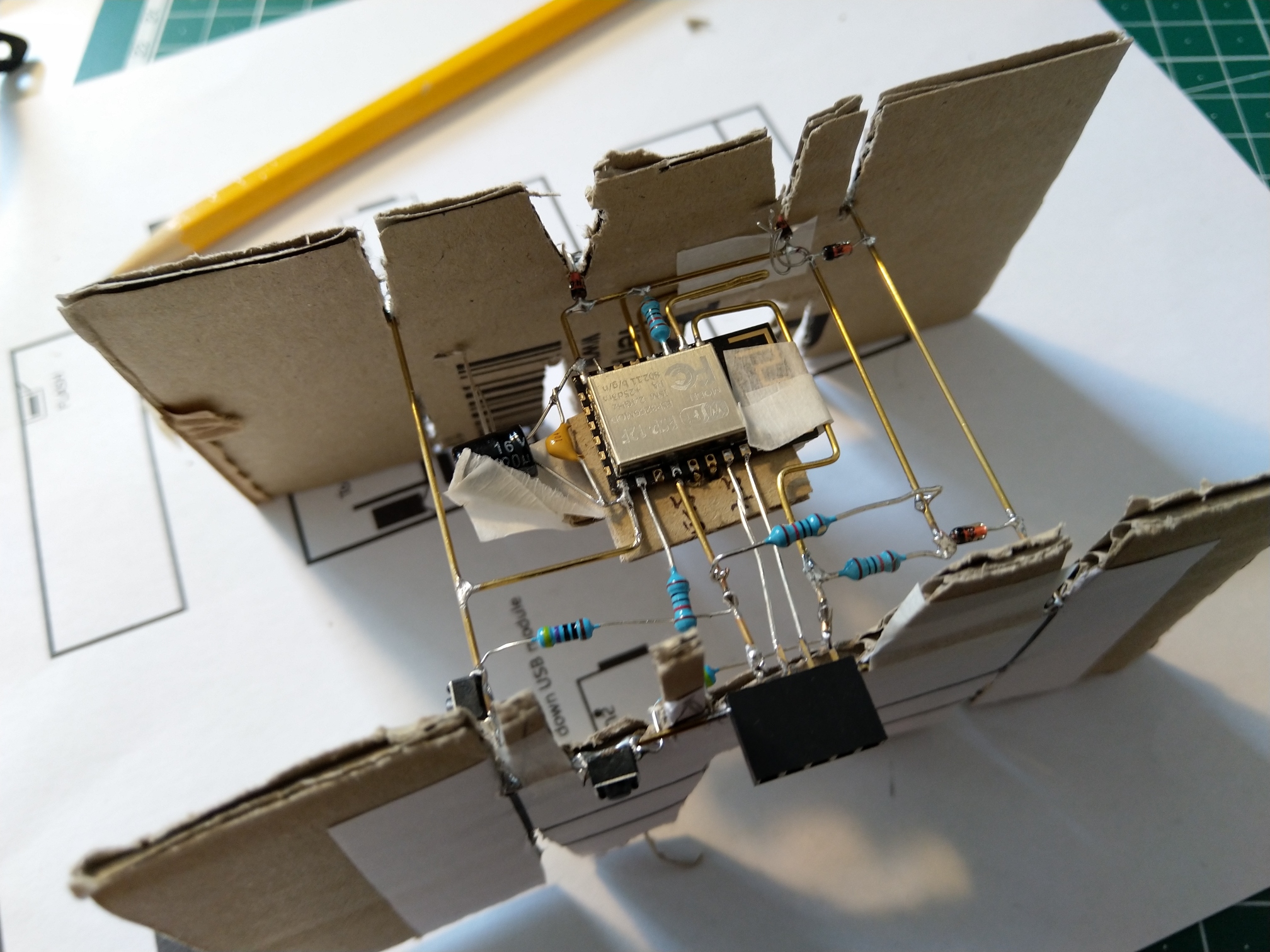
The top part is the power layer - a USB connector and a LDO regulator(LT1763) connected according to the datasheet.
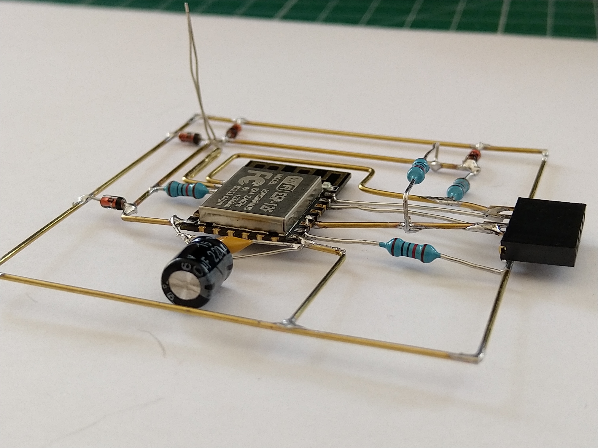
The bottom part is the top layer with ESP8266 and LED. The OLED display is not in the schematic, but it’s connected via I2C. The schematic for the ESP8266 is based on the one you can find here. I have only added buttons for Reset and Flash, LED and another capacitor.
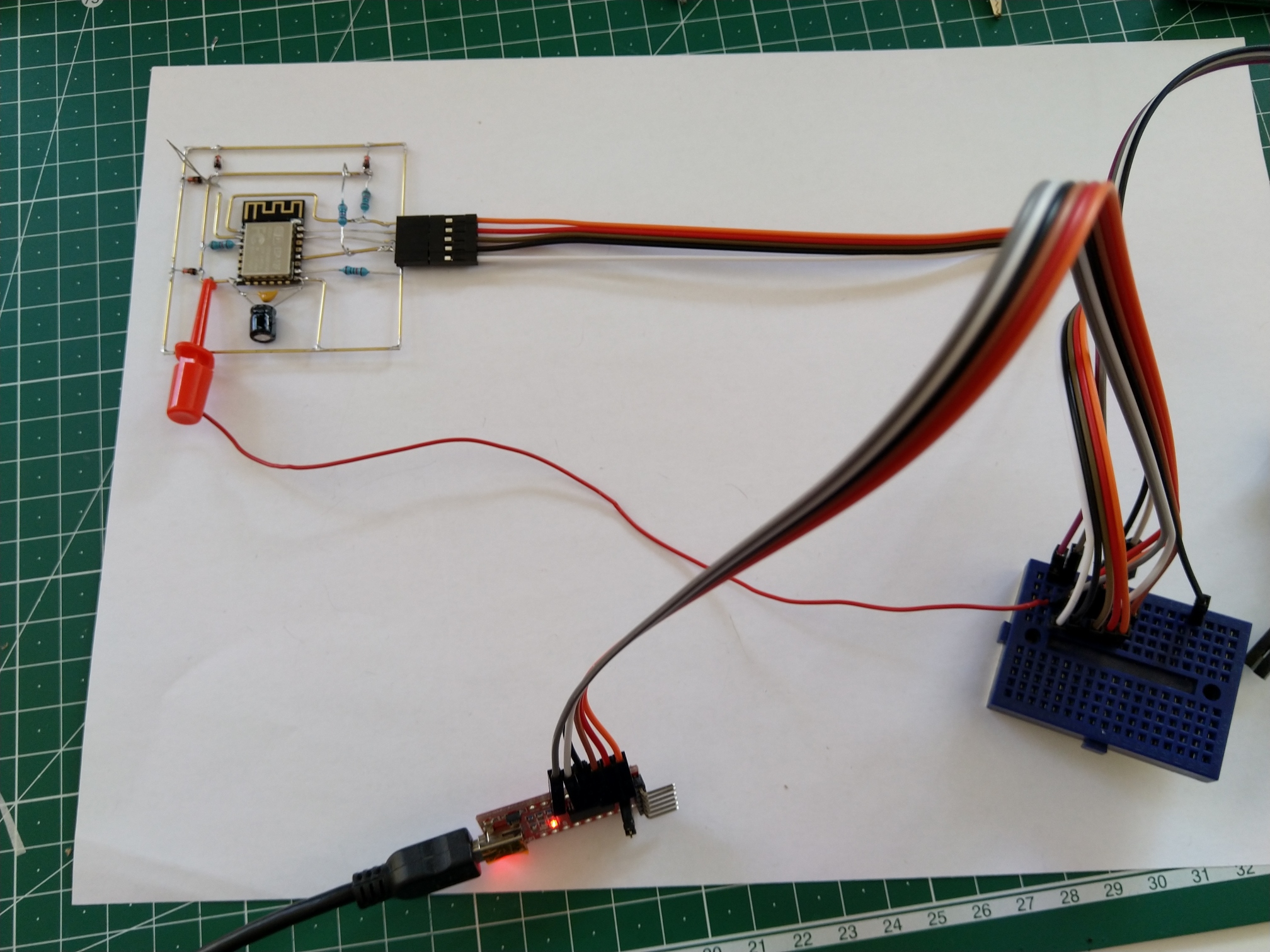
I quickly prototyped everything on a breadboard and drafted a (still not finished) firmware.
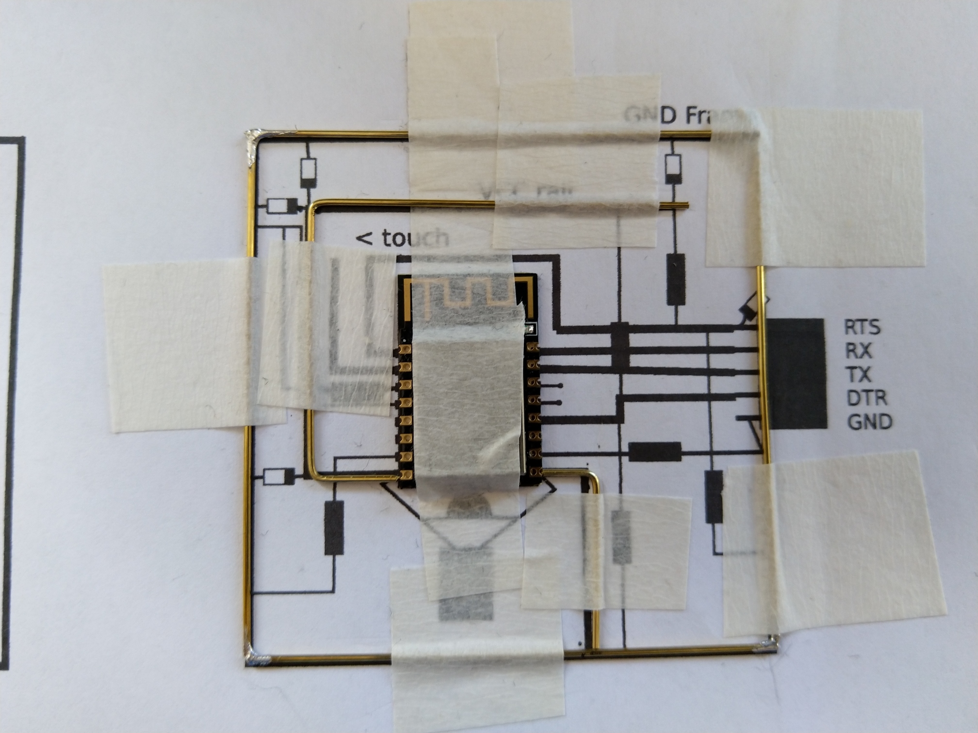
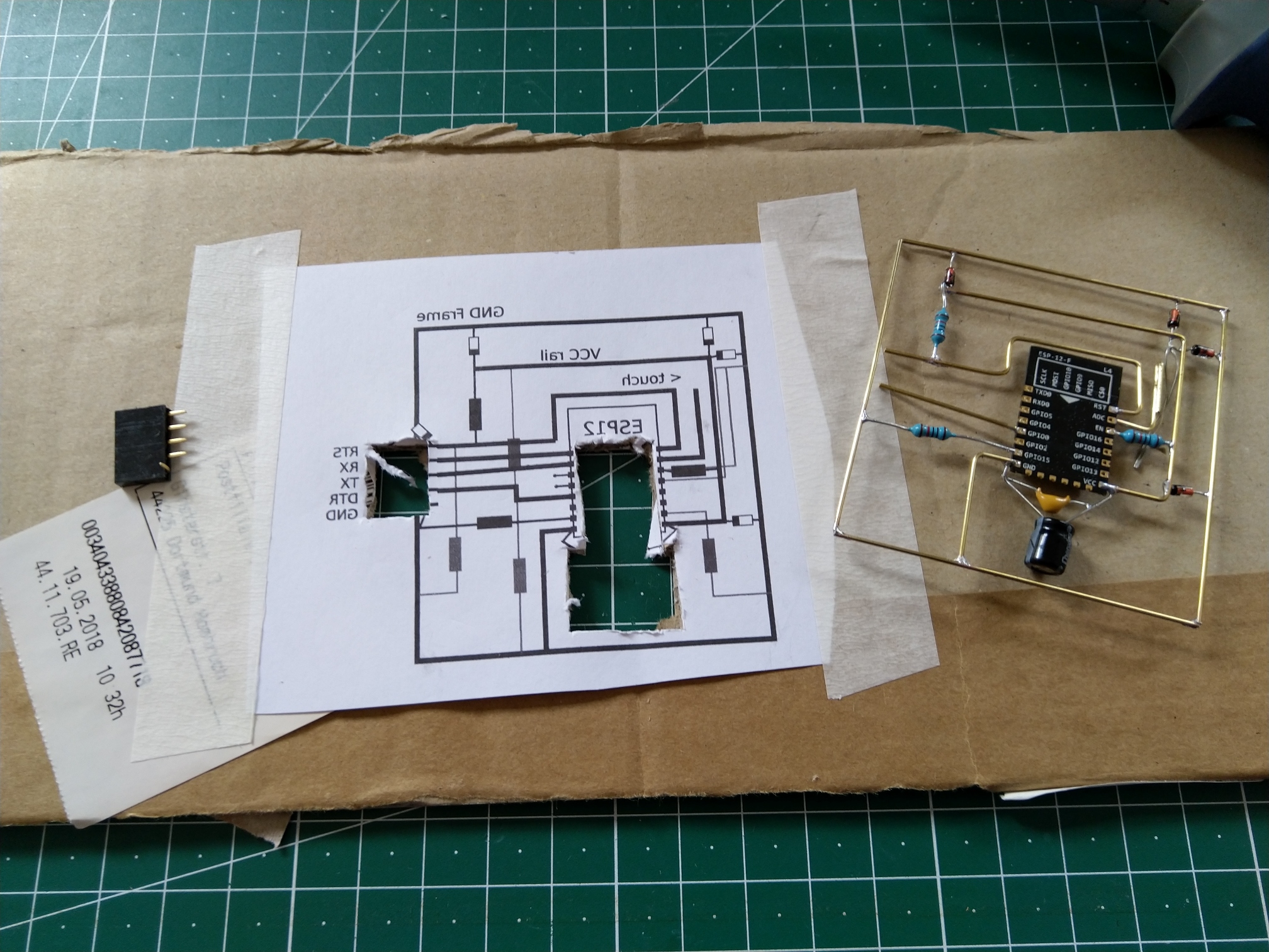
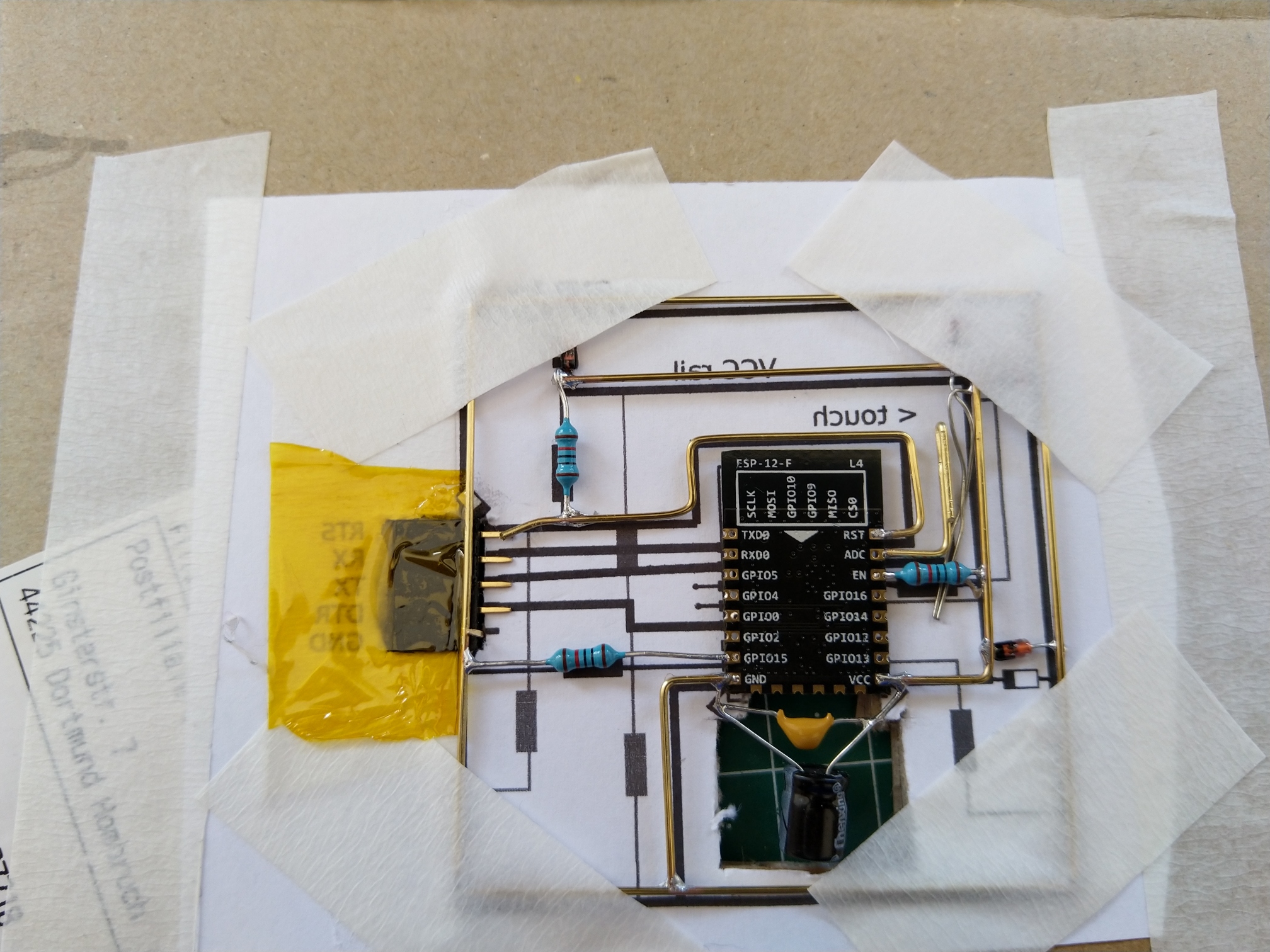
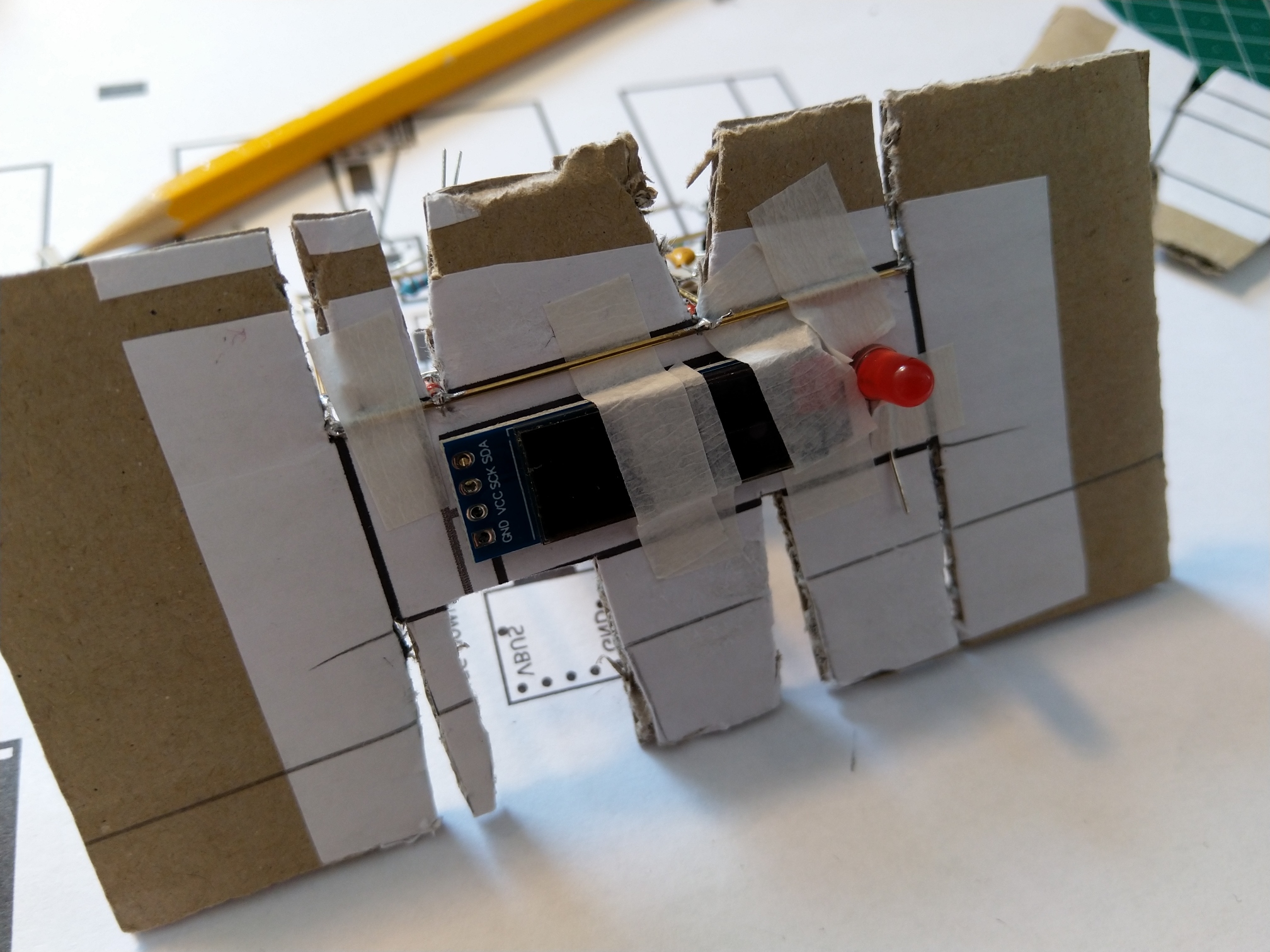
Once I figured out the layout I created templates in Inkscape and started building.
Material
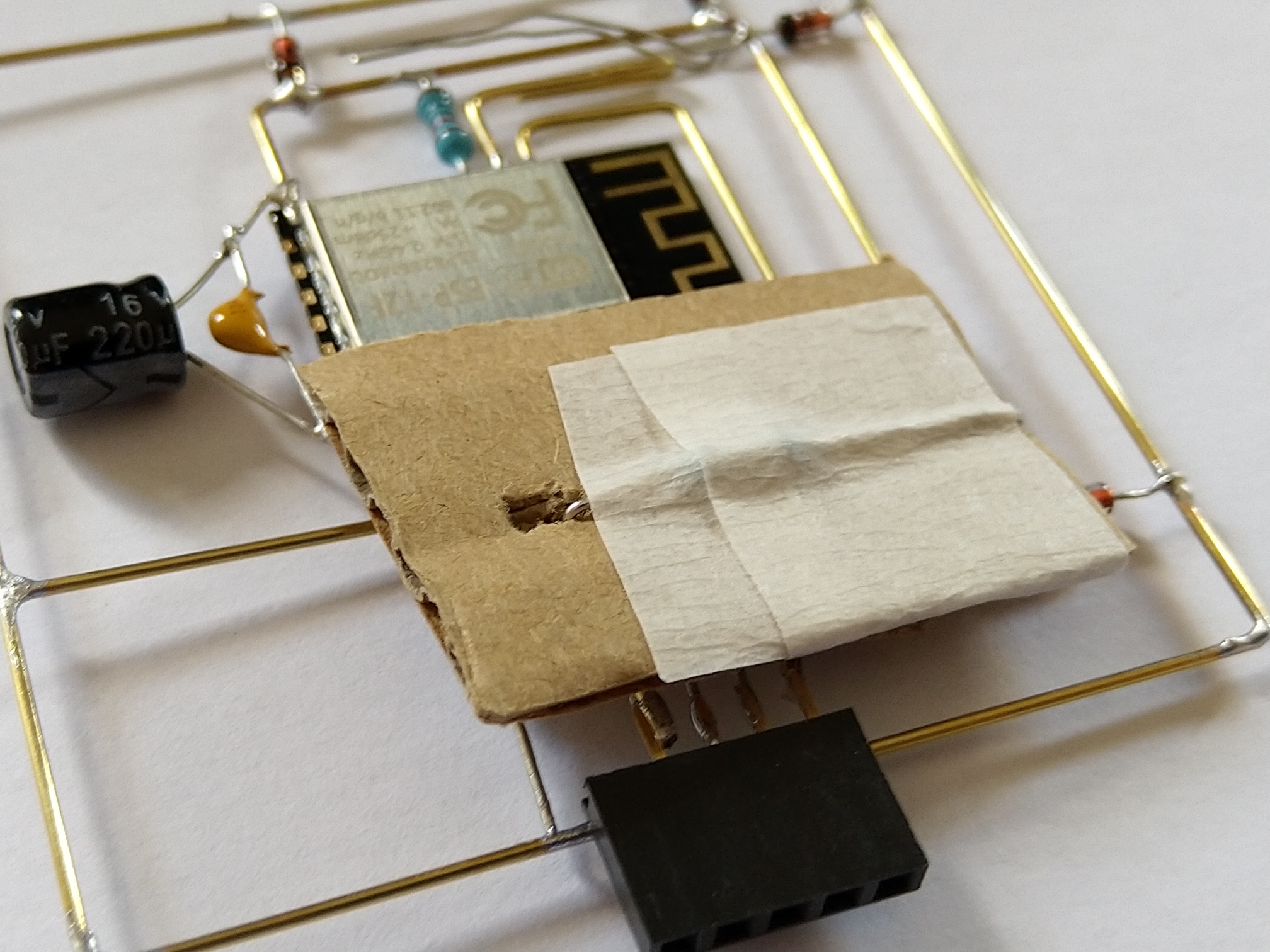
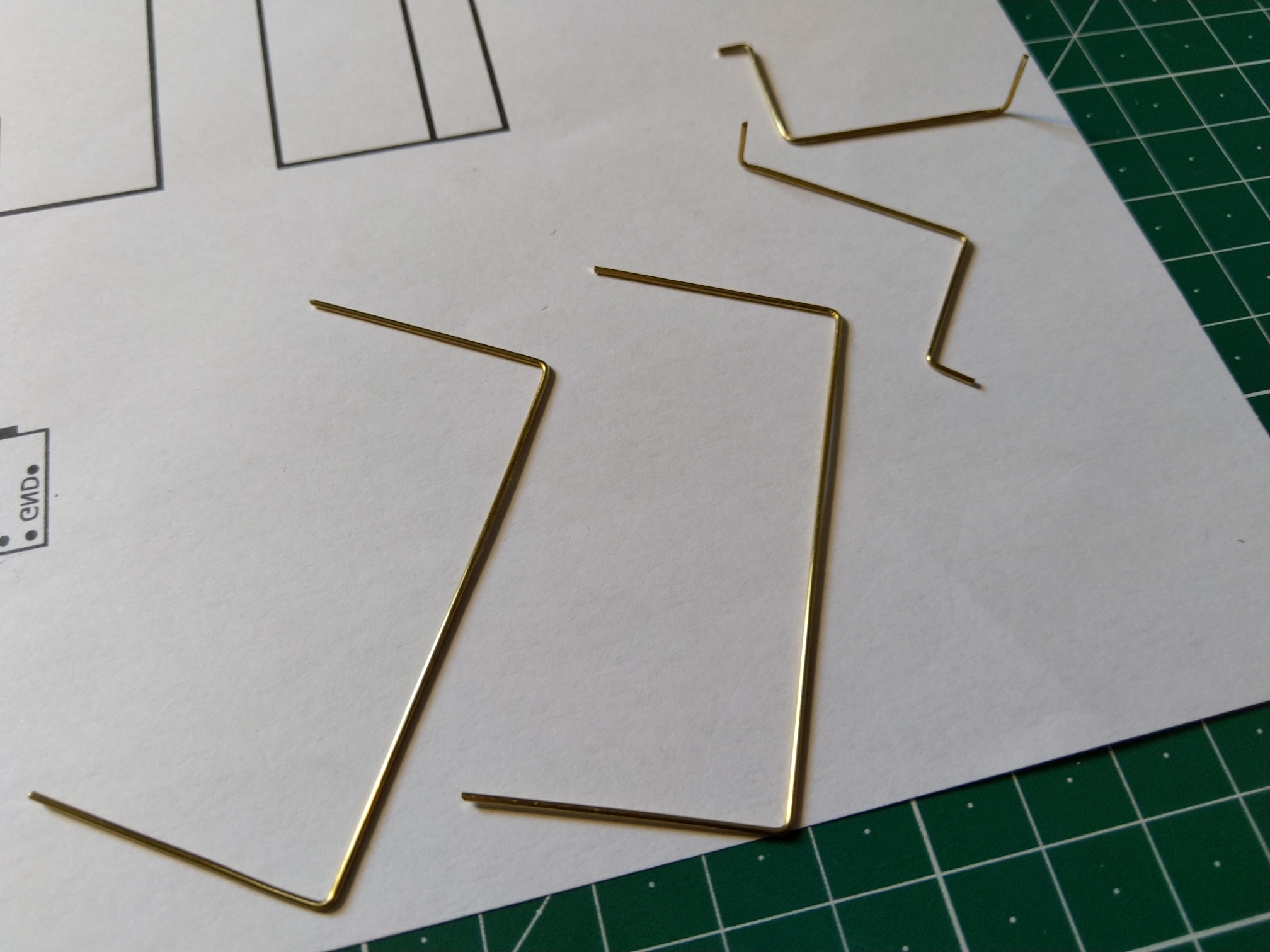
The main material for construction are 0.8 mm (1/32) brass rods. I bought mine from Modulor.de (a German e-shop). But you should be able to get them from your local hobby&model shop. Sometimes they are available on Amazon too.
Those are used by other people (mainly Jiří Praus and Mohit Bhoite) so we could consider them to be the ‘state of the art.’
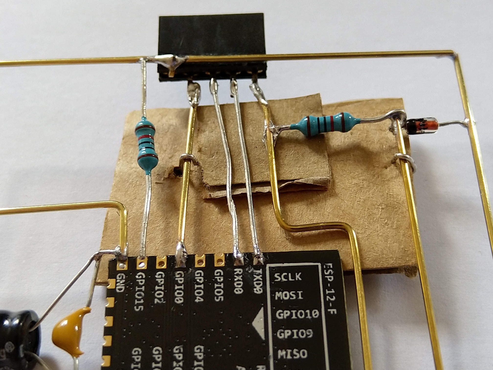
They can be a bit harder to solder, so add some flux and use a decent soldering iron. Check out this very nice guide guide to soldering brass.
Build log
This article is Part 1 in a 3-Part Series.
- Part 1 -Freeform ESP8266 OLED MQTT client
- Part 2 -ESP8266 based room-conditions monitor, Part 1
- Part 3 -ESP8266 based room-conditions monitor, part 2: PCB