When I built my Freeform ESP8266 OLED MQTT client and wrote about it I mentioned I have a long-running project which captures the data I wanted to display on the device. I call it Room Monitor and it is nothing special - a bunch of sensors connected to ESP8266 and powered with a battery. I am going to briefly sum‑up its hardware and software development in the following two articles. This one is going to cover prototyping and the next one the current (and semi-finished) PCB version.
This article is Part 2 in a 3-Part Series.
- Part 1 -Freeform ESP8266 OLED MQTT client
- Part 2 -ESP8266 based room-conditions monitor, Part 1
- Part 3 -ESP8266 based room-conditions monitor, part 2: PCB
Just because I can
When I began with all this tinkering with electronics and micro-controllers it was a very common story. I have got some Arduinos, a bunch of basic THT components, a breadboard, jumper wires, and a few sensors. Obviously, I spent some time playing with all those things, connecting them together in ways anyone could imagine.
When I had a bunch of sensors like temperature and humidity connected to a micro-controller I started thinking I could make a weather station one day. But you know, those have to be outside, protected from the environment yet still be able to capture correct values (access of air to sensors) which makes them a bit more difficult to put together. There also has to be a way how to power them and how to send the measured data (and where).
As with every complex project, I had to choose the battles I would like to fight first: powering and communication. So my weather station could stay in my room and measure values I don’t really need to know. But as I like to say: This is a hobby. Hobbies are not supposed to be practical.
The first prototype - let’s breadboard it
The first prototype was obviously on a breadboard and was build from the things I had at home.
- Wemos D1 Mini board (or clone) with ESP8266
- SHT30 breakout a temperature and humidity sensor
- BMP280 breakout a barometric pressure and temperature sensor
- a photoresistor as a light sensor
- and an I2C LCD display which was showing the measured values.
Both sensors were connected through I2C and powered by 5V (no battery yet). Data were sent using the Adafruit MQTT library to io.adafruit.com because it was easy to setup. This made the task one - communication - pretty sorted out. I spent some time writing the firmware and because I learned a bit of C++ back then I hugely over‑engineered the code.
The second prototype - battery powered
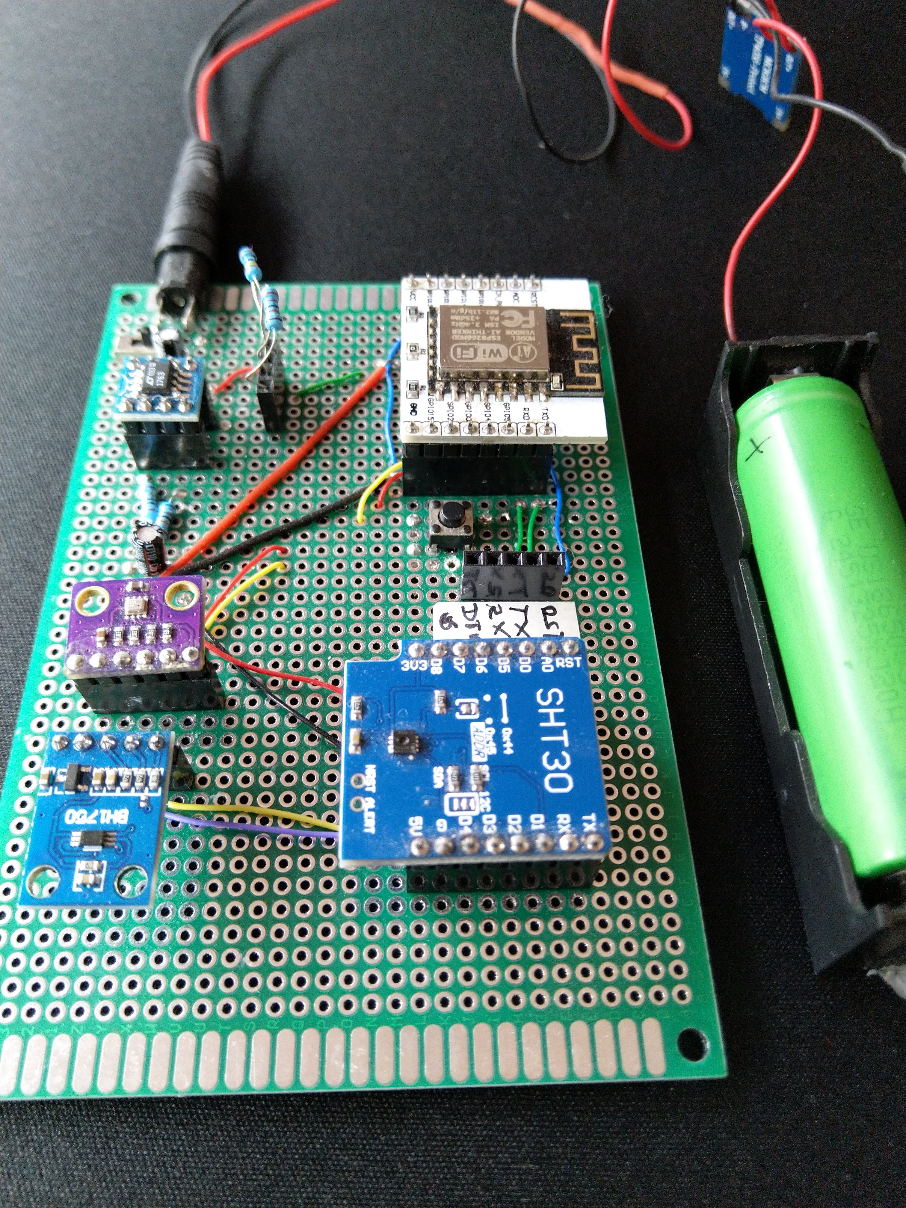
The second one was built on a piece of perfboard. Most of the components were connected to PIN headers. There was still the good old Wemos D1 MINI. The photoresistor was replaced by a breakout with BH1750 - a light intensity sensor. The display was discarded in order to save battery life.
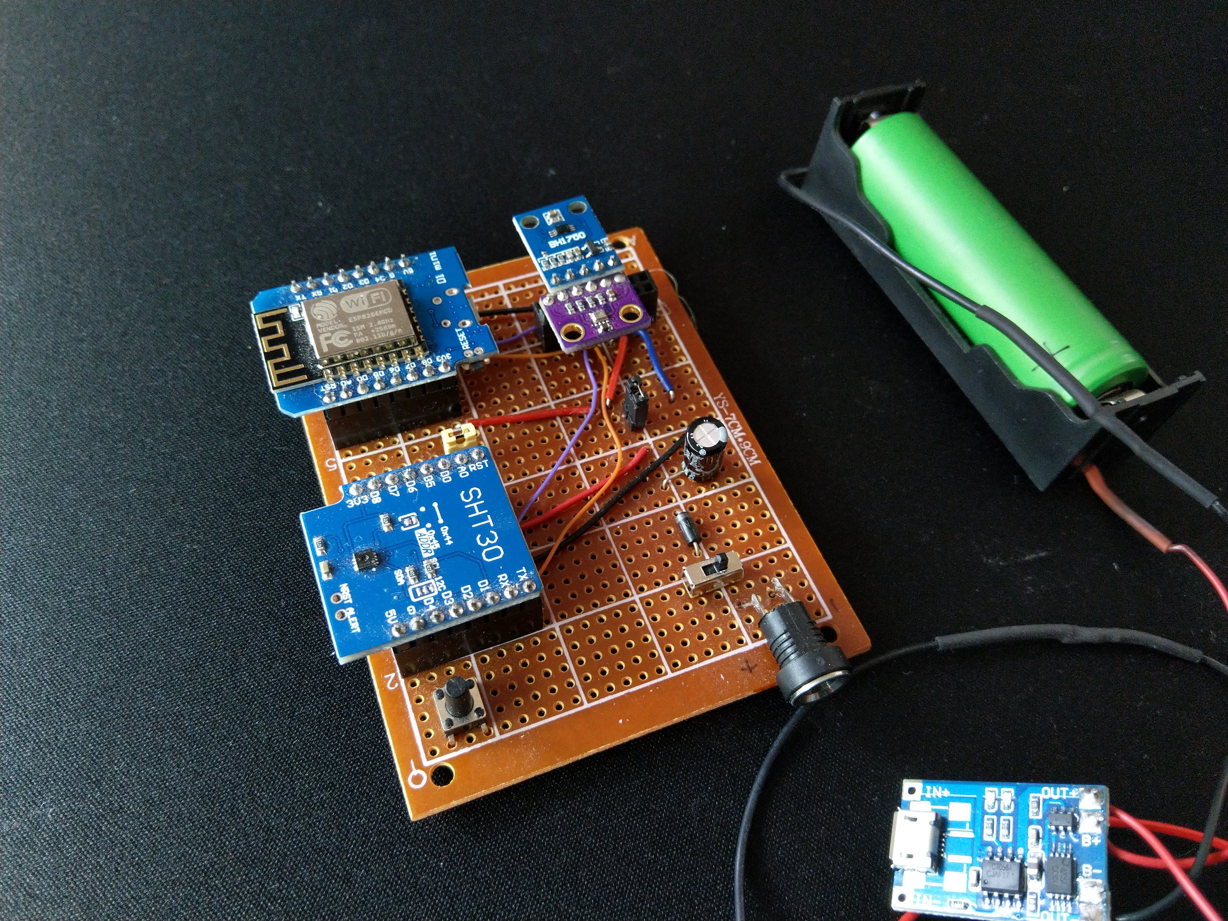
But the most important change was the power. I used one Li-On cell (18650) to power the device1. The voltage on such a cell ranges from 4.2V (fully charged) to 2.5V when the over‑discharge protection circuit shuts off. ESP8226 itself is powered by 3.3V. There is a voltage regulator on the Wemos D1 Mini board to drop 5V (e.g. from USB) to 3.3V. But you can also power the board directly by 3.3V and bypass the regulator.
I had only the raw voltage from the cell available that is too low for the voltage regulator. It’s also too high for the ESP8226, at least when charged (the supported range for ESP8226 is from 3V to 3.6V). This prototype didn’t solve this issue properly. Some voltage was dropped by a diode and other than that it was just keeping fingers crossed that ESP8266 survives working out of specification.
It worked without bigger problems for a few months and then ESP8226 died. I am not really sure why. It might have been over‑voltage but also under‑voltage when the battery was drained too much, or something completely different.
Optimizing for battery life in firmware
Nevertheless, I was able to experiment with the battery life and how it could be affected by firmware. I even made a small device to help me with that.
The best way how to make ESP8226 last long time on battery is to use deep‑sleep2 mode. In this mode, only a small part of the chip is running and the rest is completely turned off, even the content of RAM is lost during deep‑sleep. In my case this was perfect - measure and send away the data, sleep for 5 minutes and wake up again.
All that sounds easy enough, but there is some complexity in the real world. The firmware for ESP8266 has some specific behavior and some bugs which affect its power consumption. Some people already did experiments and measurements and reported what they have found.
The following links are a must‑read for anyone who wants to optimize deep‑sleep mode for ESP8226:
- Reducing WiFi power consumption on ESP8266, part 1, part2, and part3 by Erik H. Bakke.
- Series of articles about Low Power Wifi by Thorsten von Eicken which covers not only ESP8226 but even ESP32, and RTL8710. They are very detailed and very well done.
One can learn a lot of tricks from the articles above:
- Avoid the WiFi scan. Store WiFi configuration (channel, BSSID) after connecting and restore it on the next run. With a fall-back to scanning if the configuration changed meanwhile. (explained here)
- Avoid DHCP resolution. Use fixed IP address, gateway, and subnet.
- Turn off the WiFi just when the device starts, do all the work needed and then connect and send the data.
- Use
ESP.deepSleepInstant()instead ofESP.deepSleep()and use theWAKE_RF_DISABLEDflag to keep WiFi disabled when waking up. - Disable network persistence
WiFi.persistent( false )(explained here)
You can check out the current firmware at Github for details or the articles linked above for examples.
Just by applying the suggestions, I was able to get 37 days of battery life while having 5 minutes of deep‑sleep between wake ups with this prototype. That is nice but it could be better. The original, naive, implementation was worse but unfortunately, I don’t remember how long it lasted.
The third prototype - improve battery life through hardware
The power consumption is not only about firmware. It’s not only about ESP8266 either. There are other components on a dev-board3 that affect power consumption.
Mainly:
- USB to serial converter, which is powered all the time.
- Voltage regulator (5V->3.3V) which also uses some power when used.
- Depending on the board, some LEDs or other components on the board.
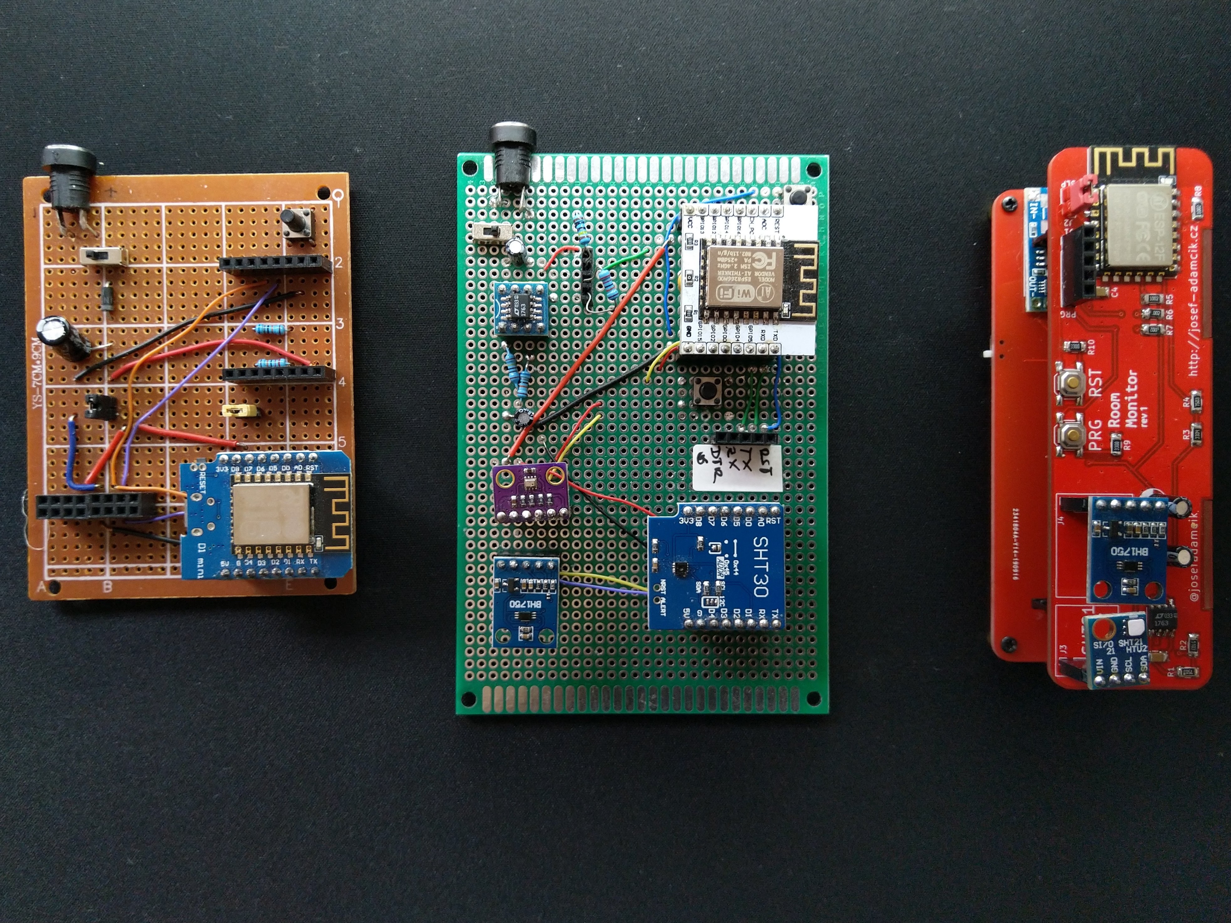
The next step was to use ESP8266 without a dev-board to have better control over power consumption. I found cute breakout boards for ESP8266 (link to Aliexpress, not an affiliate link) which allowed me to do some prototyping.
This requires to use external FTDI board for programming and communication through serial (for example reading of messages sent through Serial.print for debugging). ESP8226 has support for Over-The-Air updates so normally you would need to use FTDI only for the first flash and all the next ones can be done through OTA. You can see a PIN header with labels for FTDI on the image above.
Powering properly - picking a voltage regulator
Another change for this prototype was an introduction of a voltage regulator to convert variable voltage from a Li-On cell to a stable voltage for ESP8226 and other components.
There are several criteria we need to pay attention to when picking the regulator:
Power drain
They also consume power and they will drain some power even when the ESP8226 sleeps. This is called “Quiescent Current” in a datasheet.
Output current
How big output current the regulator can provide. ESP8226 can take around 140 mA on average when working, but it can drain up to 350 mA when communicating4.
Dropout voltage
Dropout voltage is the minimal difference between the output voltage and the input voltage. For example, if I want output voltage 3.3V and the regulator has a dropout voltage 1V I would have to supply least 4.3V otherwise the regulator will fail to provide the desired voltage. This is very important when we run on battery which has a voltage range from 4.2 to, let’s say, ~3.0V 5. If we had a regulator with a dropout voltage like the 1V from the example above, it wouldn’t be able to supply 3.3V when powered with one Li-On cell. We would have to use at least 2 cells in series.
So I need an LDO (Low-Dropout) regulator with very small dropout. Keep in mind this also changes with the current we drain and the dropout tends to be bigger with the bigger current. The smaller dropout we have, the more power we would be able to squeeze from the cell.
Output voltage
Every LDO has either fixed or variable output voltage. The straightforward pick would be 3.3V for ESP8226. But it is rated to work in a range from 3V to 3.6V. So we could also use 3V and have more room for the dropout voltage of our regulator.
Choosing the voltage regulator
In the end, I picked LT1763 from Linear Technology (datasheet) in the variable output voltage variant.
- It can be used as a 3V regulator
- It has 0.3V dropout voltage6, so the device can work until the cell discharges to 3.3V. That’s sufficient because it doesn’t really make sense to go lower.
- It can supply up to 500mA
- It has low Quiescent Current - 30μA
But, is it really better?
The final battery life jumped to 57 days. That is 20 days (54%) more than the previous prototype. That is a significant improvement.
Next time
The third prototype was very successful and I decided to give it some nicer form. The next article will cover a design and a build of a custom PCB with some unusual shape.
Footnotes
-
It may case it is Sony US18650V3 rated for 2250mAh. Protected and charged through a TP4056-based module with over-discharge and over-current protection. Never use those cells without a proper protection circuit! ↩
-
ESP8226 has several sleep modes but the internet is full of articles about them so I am not going to explain them all. ↩
-
Wemos D1 Mini, in my case. ↩
-
You can find various information and speculation about the maximal power consumption of an ESP8226 module. The values I used are from measurements done by Thorsten von Eicken in his article. ↩
-
The protection circuit will turn it off at 2.5V. But you should stop draining the power sooner. The sooner you stop the longer life is your cell going to have. It’s also important to realize that the voltage drops very quickly at the end of the voltage range. I don’t have any nice graph to embed in the article, but you can look for example here for a graph from discharge testing of the cell. The curve starts to descend very quickly when 3.2V is reached. Of course, the real shape of the curve depends on the cell and on the current being drained and so on. ↩
-
300mV for 500mA. It’s even smaller for smaller currents. ↩
This article is Part 2 in a 3-Part Series.
- Part 1 -Freeform ESP8266 OLED MQTT client
- Part 2 -ESP8266 based room-conditions monitor, Part 1
- Part 3 -ESP8266 based room-conditions monitor, part 2: PCB