A story about how I was reminded that impatience and impetuosity can backfire when dealing with hardware.
When I dabble with electronics and those homemade devices without purpose, new ideas for projects tend to emerge from one another.
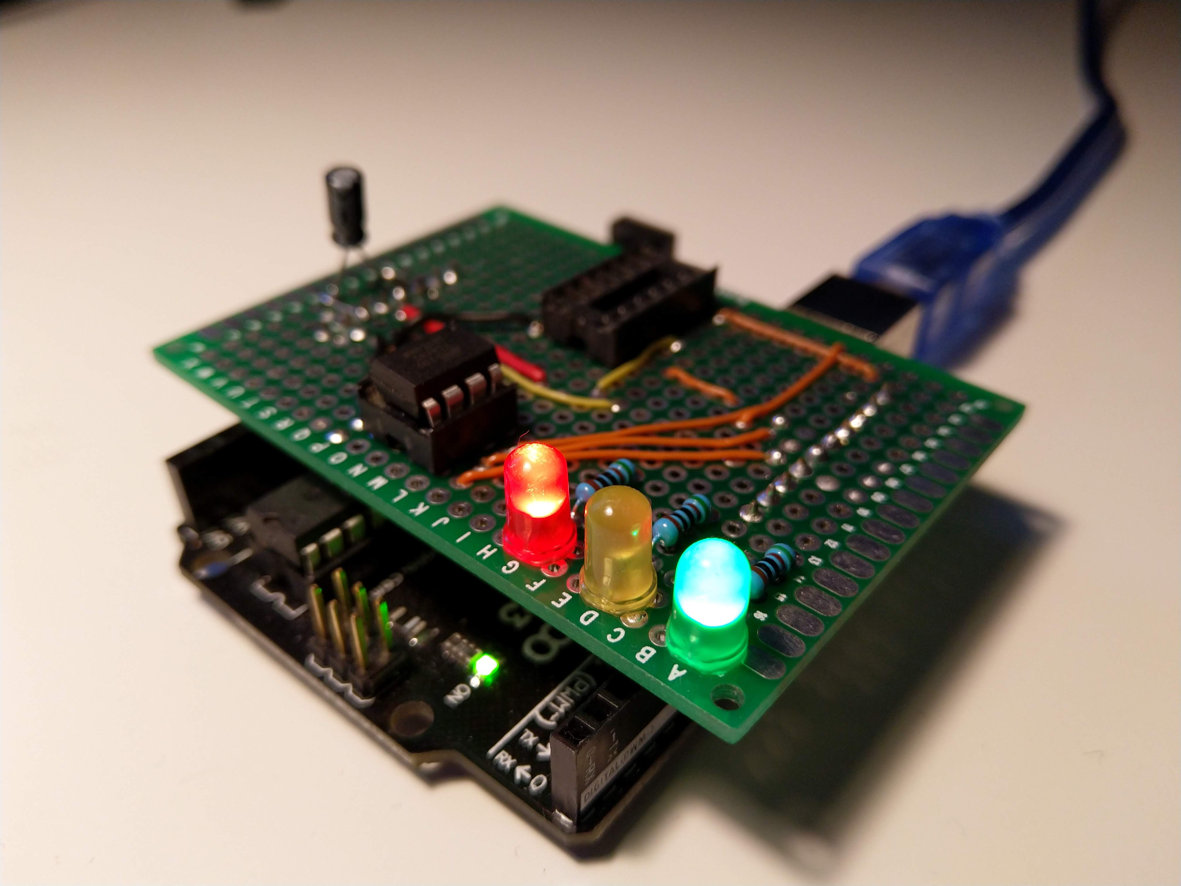
For example, when I was working on the LED cube I decided to use Attiny84 micro-controller to drive it. And because of that, I got an idea to build a simple Arduino shield to help with programming of Attiny84 and Attiny85 micro-controllers.
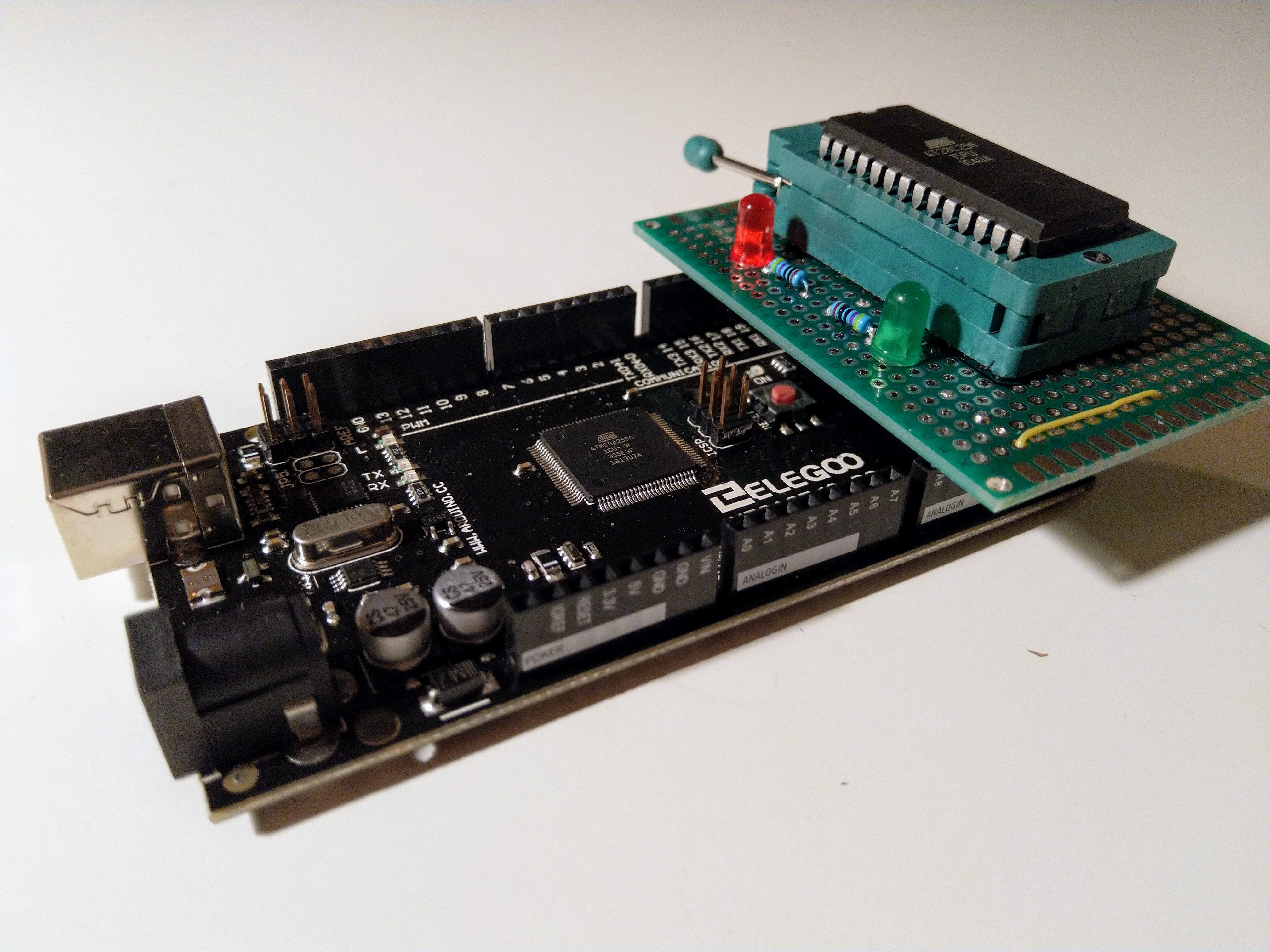
When I was building an 8-bit computer with 8085 CPU Omen Alpha (designed by Martin Maly), I needed to program EEPROM. I made a rough programmer using a breadboard and jumper wires but that was annoying to use so I decided to build a simple EEPROM programmer shield for Arduino Mega (based on a design by oddbloke).
Idea and motivation - the Room monitor project
One of my ongoing projects is a simple device which combines a few sensors (temperature, light, humidity) and an ESP8266 micro-controller (datasheet) (which has wifi capability). The device measures indoor conditions and sends data to an online dashboard. It’s meant to be learning project which may one day evolve into an outdoor meteorological station. It is battery powered (li-on) and part of the fun is trying to make it run as long as possible without recharging. Update: I have written an article about this project
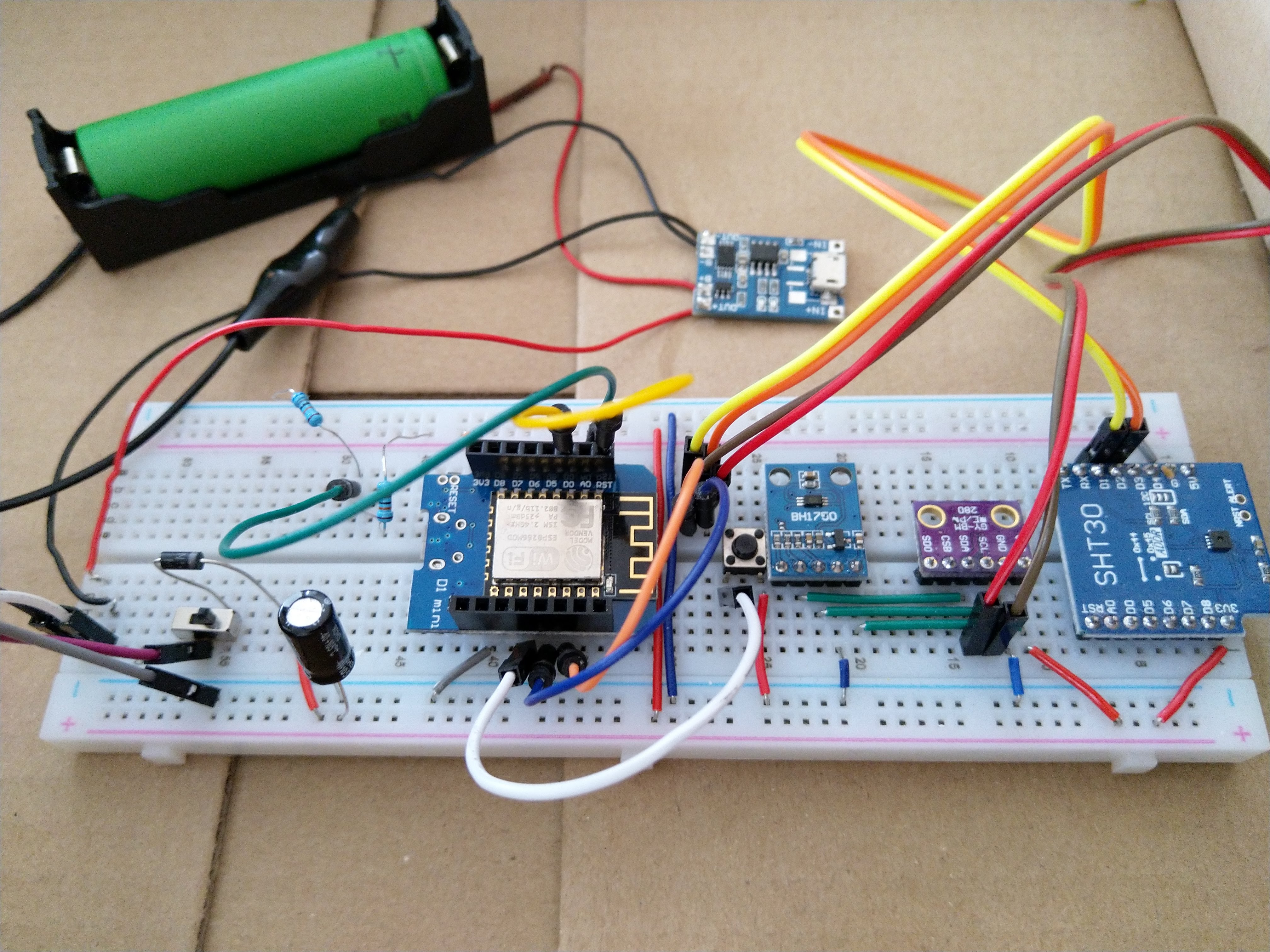
The micro-controller has several sleep-modes and other functions that are supposed to help with energy consumption. But there are many possible combinations and some quirks and therefore a lot of experimentation is required. But how to test this? How to compare different configurations and solutions in order to choose the best one? Well, you cannot just compare momentary current consumption since it changes a lot when the device activates after sleep when it communicates via WIFI etc. It’s also not practical to compare overall battery life since it’s measured in weeks.
I do not have any tools that would help me with such a task. But a simple device which would be able to measure voltage and current in regular intervals and store the agregated result over time (energy) would do the job, wouldn’t it?
Building blocks of Power measurement device
I found a neat breakout with INA219. INA219 (datasheet) is an IC which supports such measurement and can communicate via I2C bus. The breakout module also contains other components you need in order to make the IC work. Great!
Now I need just to connect some micro-controller and maybe a display and a few buttons and write a firmware. And again, a neat little side project was born.
Prototyping
I prototyped the solution quickly with Arduino and started working on the firmware. I must admit I went a bit crazy with the code. I over-engineered things a lot, tried to capture everything in classes and separate things properly as I am used to in my daily job (being a software developer). At least kind of, because I am not a particularly skilled C/C++ programmer. In the end, I wrote a lot of code and got a bit bored before I finished the firmware. But the main functionality was complete. I just needed to finish a menu in which I would be able to adjust some settings - an interval between measurements, selected calibration for INA219, and I also want to be able to reset the measured energy value.
Quick jump to the final hardware
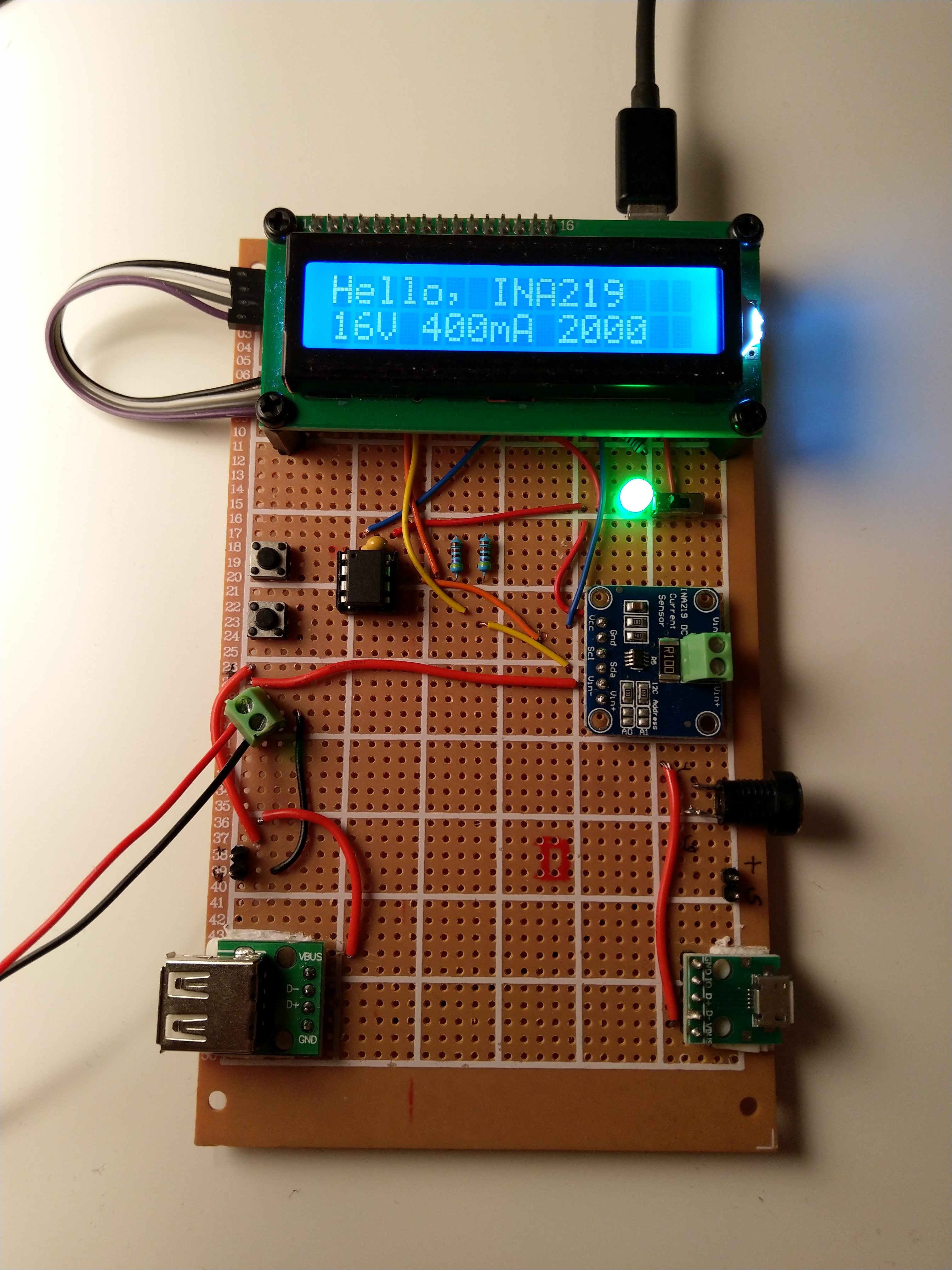
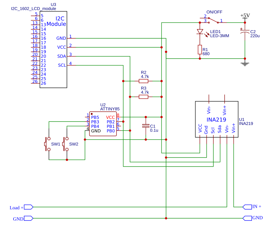
I was impatient (again) and started sketching the final circuit which I wanted to solder on a prototyping board. I decided I would like to use Attiny85 as micro-controller. The device requires just 2 pins for buttons and another 2 for I2C and Attiny85 has 6 IO pins. I also had good experience with Attiny84 which I used for my LCD cube (the only difference between 84 and 85 is that 84 has more pins).
Again, I was impatient. So I actually soldered the things together without building a prototype with Attiny85. And that was a mistake. But it looks neat, doesn’t it?
Problem #1 - program memory
As soon as I tried to upload the firmware to the Attiny85 I realized that it’s too big. Attiny85 has only 8 kilobytes of program memory and my firmware was roughly 200 bytes bigger. What now? It took some experimentation but I have found out that if I remove all usages of the String class from the Arduino SDK I can save 1 kB.
PROGRAM: [========= ] 94.9% (used 7776 bytes from 8192 bytes)
Great!
Problem #2 - interrupt pins
I have used 2 buttons to control my prototype. Why two and not, for example, four? Because Arduino UNO has 2 interrupt pins and therefore I could easily hook those buttons to them.
But oops, Attiny85 has only one interrupt pin. Fortunately, there are also so-called pin change interrupts1. They are not supported by Arduino SDK so you need to call the underlying AVR SDK in order to use them. They are also a little bit harder to use since there is only one service routine for all pins you want to observe for change interrupts.
But, in the end, I managed to make it work. Great!
Problem #3 - I2C bus
I2C is a serial bus. It’s widely used and Arduino UNO has hardware support for it. Regarding the Arduino SDK the Wire library is the API for I2C.
Well, guess what, Attiny85 does not support I2C natively, at least not in the same way as Arduino does. There is some support in the Arduino core for Attiny85 I am using but that didn’t seem to work with my LCD. There were just random characters all over the place.
I tried to use other libraries, soldered pull up resistors to I2C lines2.
In the end, I finally solved the problem by using the TinyWire library. I had to modify libraries for LCD and INA219 so they actually use TinyWire instead of Wire.
Finally, everything was working the same way as on the Arduino. Now it was time to finish the firmware.
But maybe this problem was actually caused by something different. Wait for the next one which may have been the real cause of the broken behaviour I observed.
Problem #4 - RAM
I continued to work on the menu. As I added more strings Attiny85 started to do crazy things. Sometimes it just restarted. Sometimes it got into restart loops. Sometimes it kind of worked but LCD again displaying random characters.
This problem gave me the most trouble because I basically didn’t have an idea what’s happening. I am honestly still not 100% sure if I understand the problem correctly.
During debugging I noticed that the problem appears when I have more data in my array which contained strings (You know, C character arrays) for my display. I was not using PROGMEM but my data size was still smaller than RAM and I had was able to upload the firmware to the Attiny85 without problems. But the more data I added the worse results I get.
In the end, I found out that the behaviour I observed might be caused by stack collision. The idea is, that as the program runs the stack (which grows from the end of the memory space) overrides your heap and/or static data in memory and that causes trouble.
So I did the extra work and moved as much data as I could into PROGMEM. That helped and I was able to finish my firmware. You can check the result on Github, but beware, it’s not nice.
DATA:    [======    ]  55.5% (used 284 bytes from 512 bytes)
PROGRAM: [========= ]  94.9% (used 7776 bytes from 8192 bytes)
Happy end
Even though it was a bit frustrating in the end it was a great lesson for me. I should be so more patient and careful when dealing with hardware. Those quick and dirty trial-and-error iterations I am so comfortable with when it comes to software development just don’t work when it comes to hacking hardware.
And a short video.
Footnotes
-
Here is a really nice article about pin change interrupts and Arduino and here another one for Attiny85 ↩
-
Such resistors are required by I2C but you don’t need to add them when you use Arduino UNO since they are already part of the microcontroller. But I have found that it’s suggested to add them when you need to use I2c with Attiny85. ↩