I made a LED cube. A silly thing that blinks a lot and is controlled by programmable microcontroller. But why? And how?
How did I get here?
I must admit that I am quite new to all this home-made-electronics-for-fun. Although I studied electronics and computer systems on secondary school, I have never tried playing with components at home. I focused on programming since those early times.
But earlier this year I read a book from Czech blogger/writer Martin Maly (unfortunately (for prospective non-Czech-speaking reader) the book is in Czech language). I tried the book because I enjoy blog posts and articles written by Martin. And as I was reading it, a strong urge to try something, to build something, started to grow inside me.
So I ordered a lot of basic components and ICs from Aliexpress (of course!) and Amazon. I started to play and having fun. Several months passed, and I am still enjoying my new hobby and I spend time with electronics components and Arduinos, ATtinys, ESP8266, and so on. Small yellow envelopes from china come in continuous stream and make me happy every week.
LED Cube
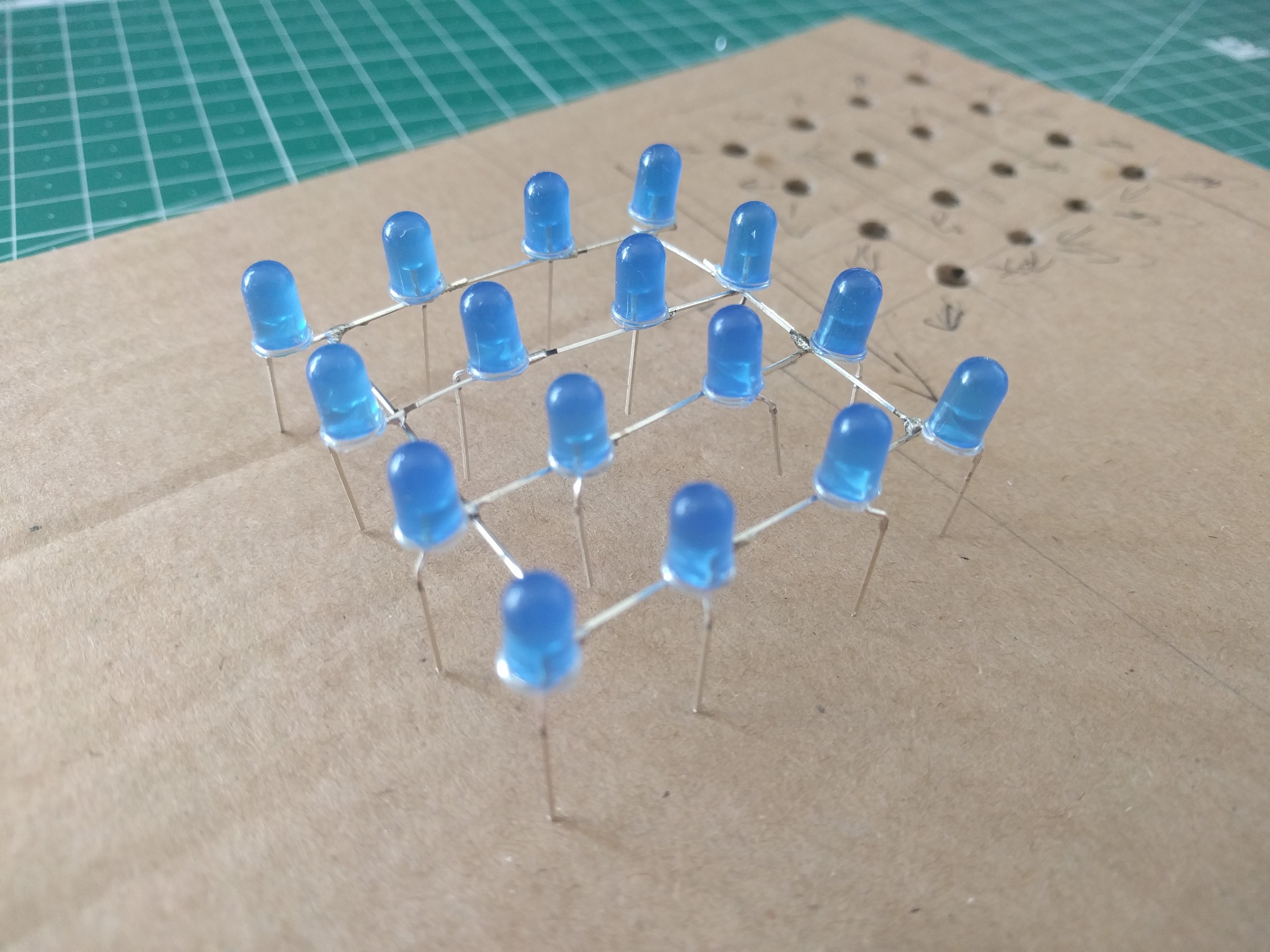
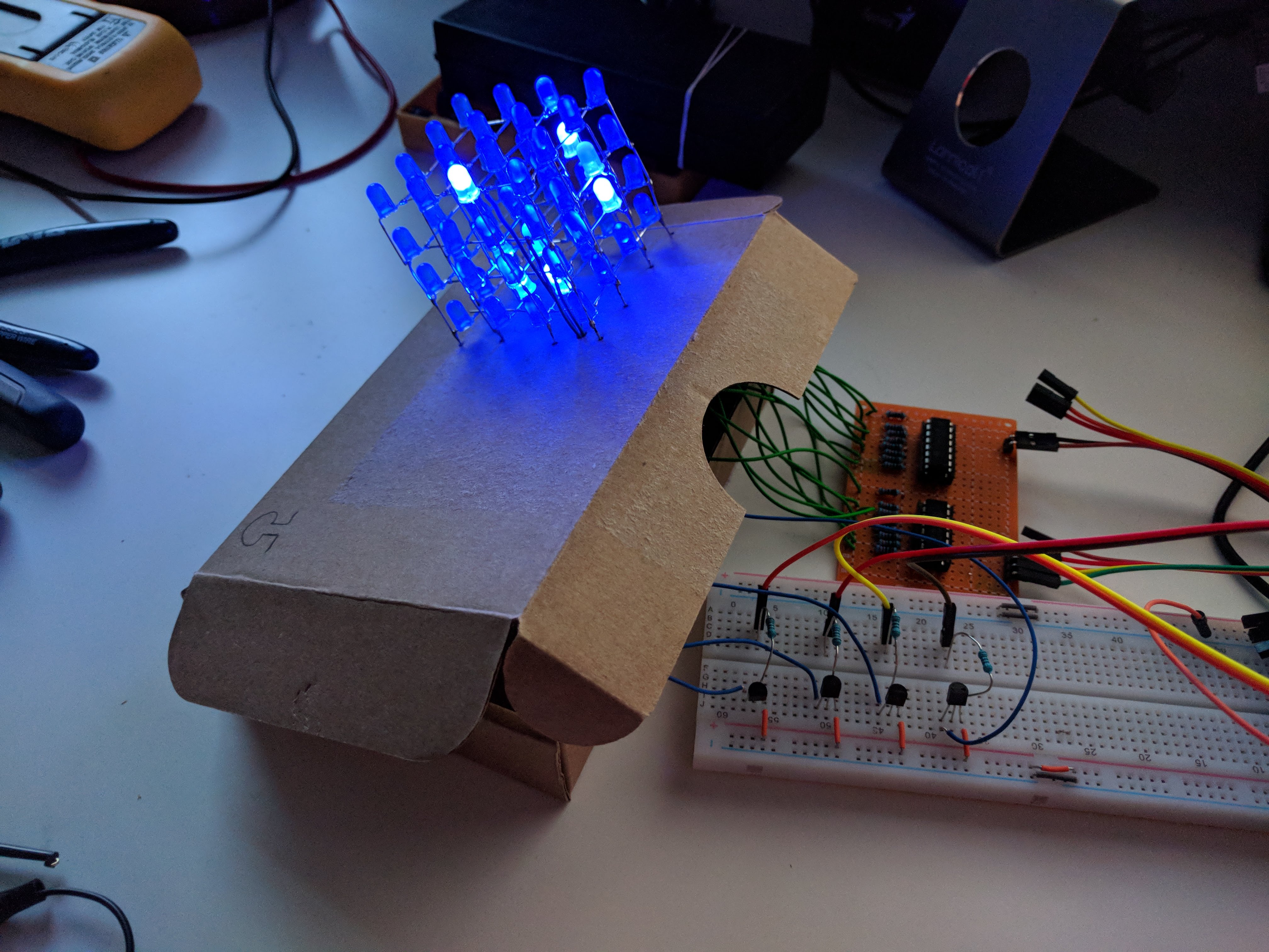
LED cubes are very popular beginner project. But at the beginning I considered that blinking cube is lame and not worth the effort. But, you know, time passed. I began to solder and had trouble with it, so I thought: “I must practice”. And of course, LED cube is an obvious candidate, when you want to practice soldering. So here it is. It’s actually my first really finished project - it has an enclosure!
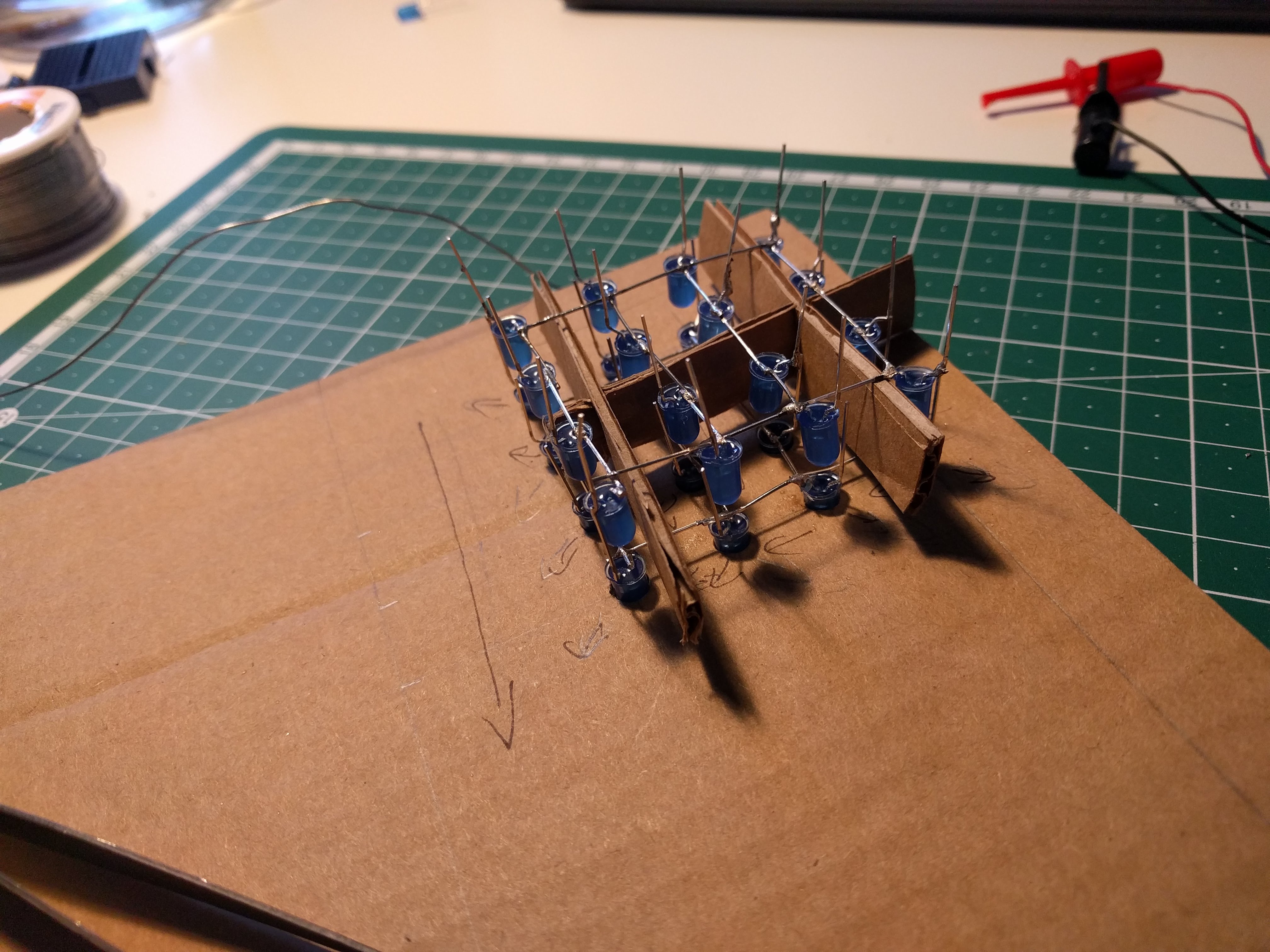
It is a 4x4x4 cube, pretty small, because my LEDs had quite short legs. I am not going to explain basic principles for designing and building those cubes, there are plenty of tutorials and guides available online (such as this or this). I am going to focus on those less usual properties of my approach.
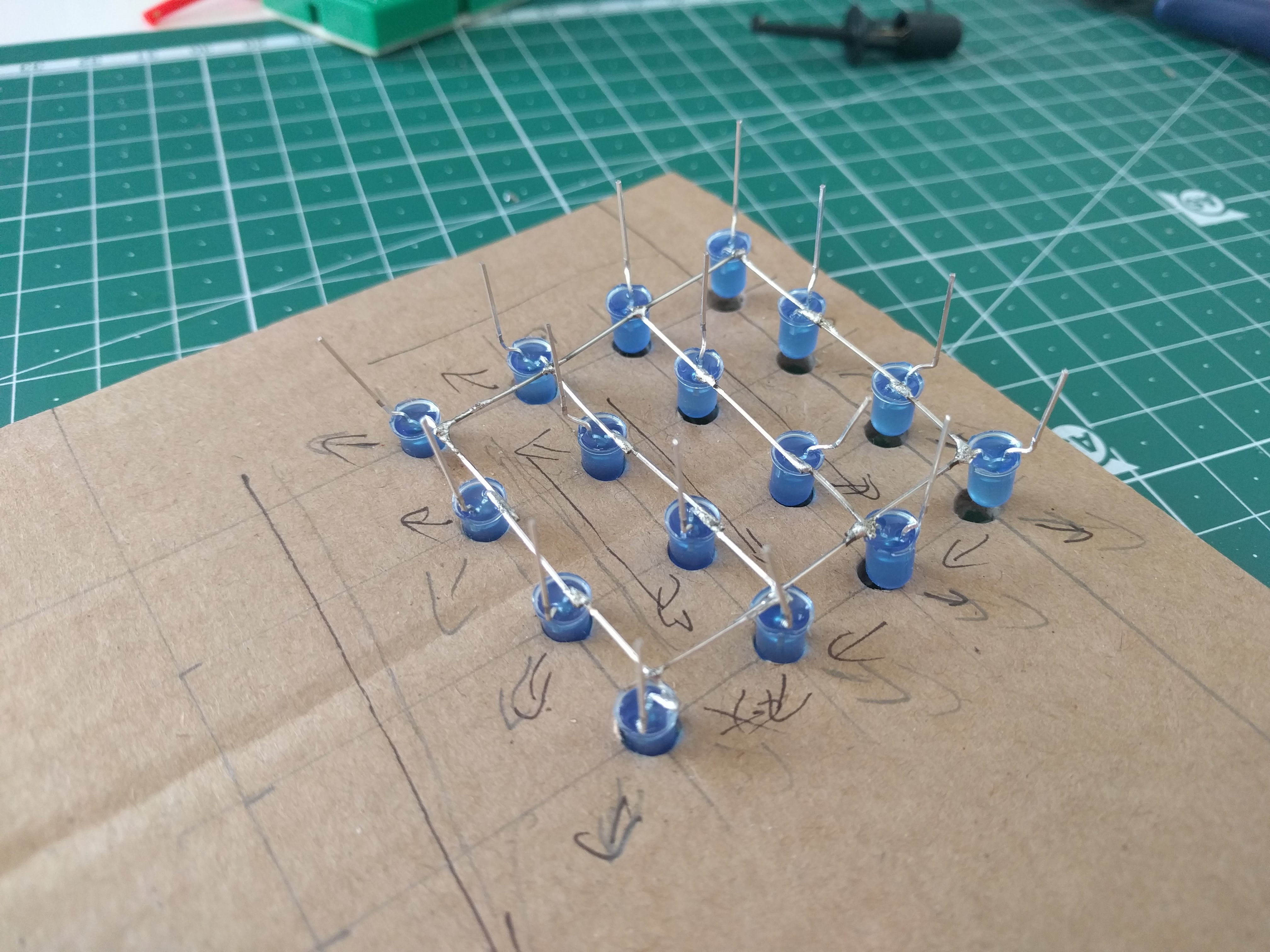
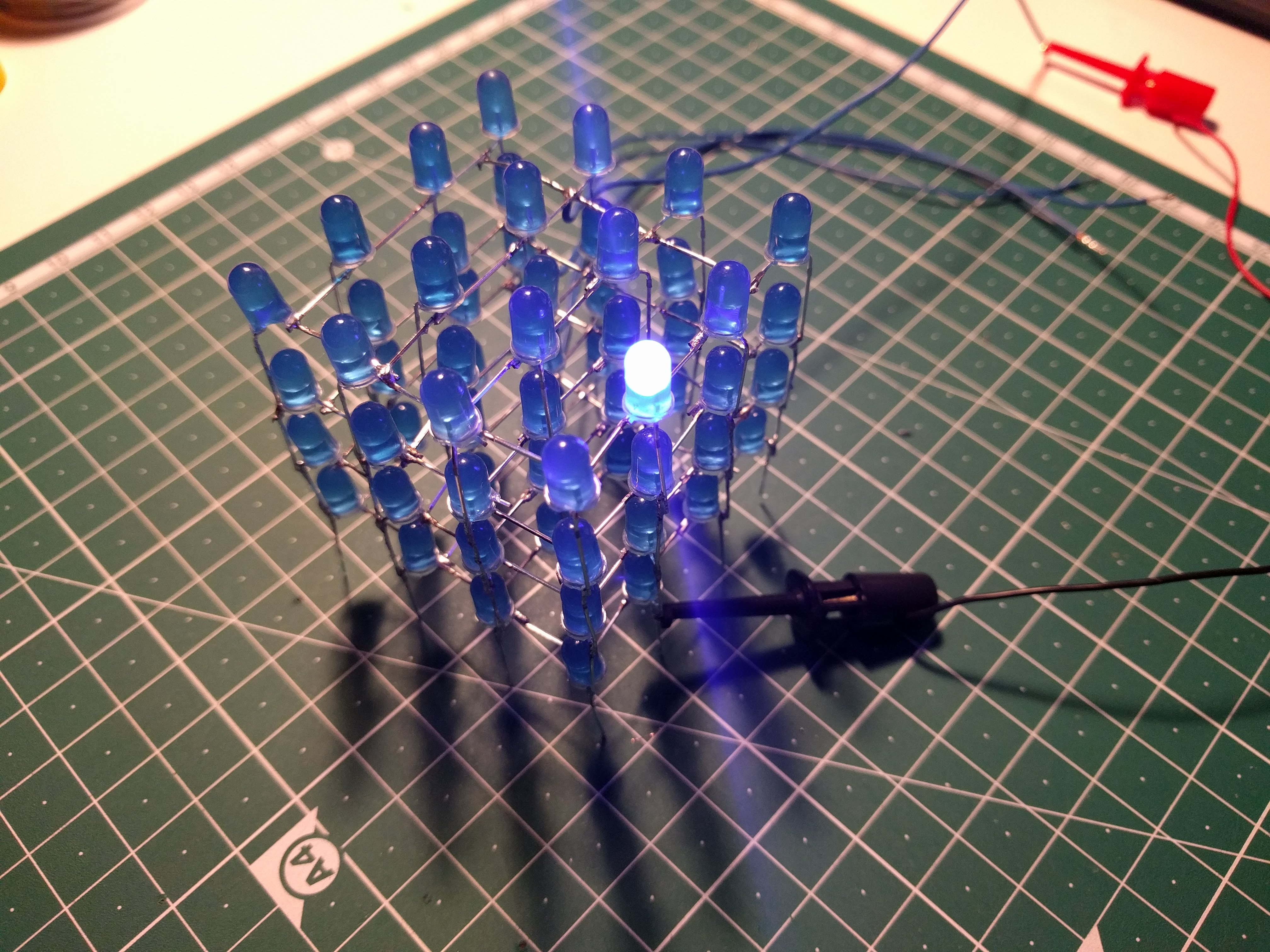
The most important thing is to be able to light one LED in a cube. When we switch selected diode quickly, we can create a persistence of vision effect and therefore a pattern or an animation.
The trick is to connect all the diodes in a column together (in my case their cathodes) and all the diodes in a level (their anodes) together. When you want to select (= turn on) a diode in a particular column, you’ll connect the column to the ground (other columns are HIGH), and diodes level to HIGH (and, of course, there should be a current limiting resistor somewhere).
That gives us 16 columns and 4 levels. That’s 20 signals, but ATtiny84 has only 12 available control PINs. For example an Arduino UNO board has exactly 20 pins, so you can use it without another integrated circuit.
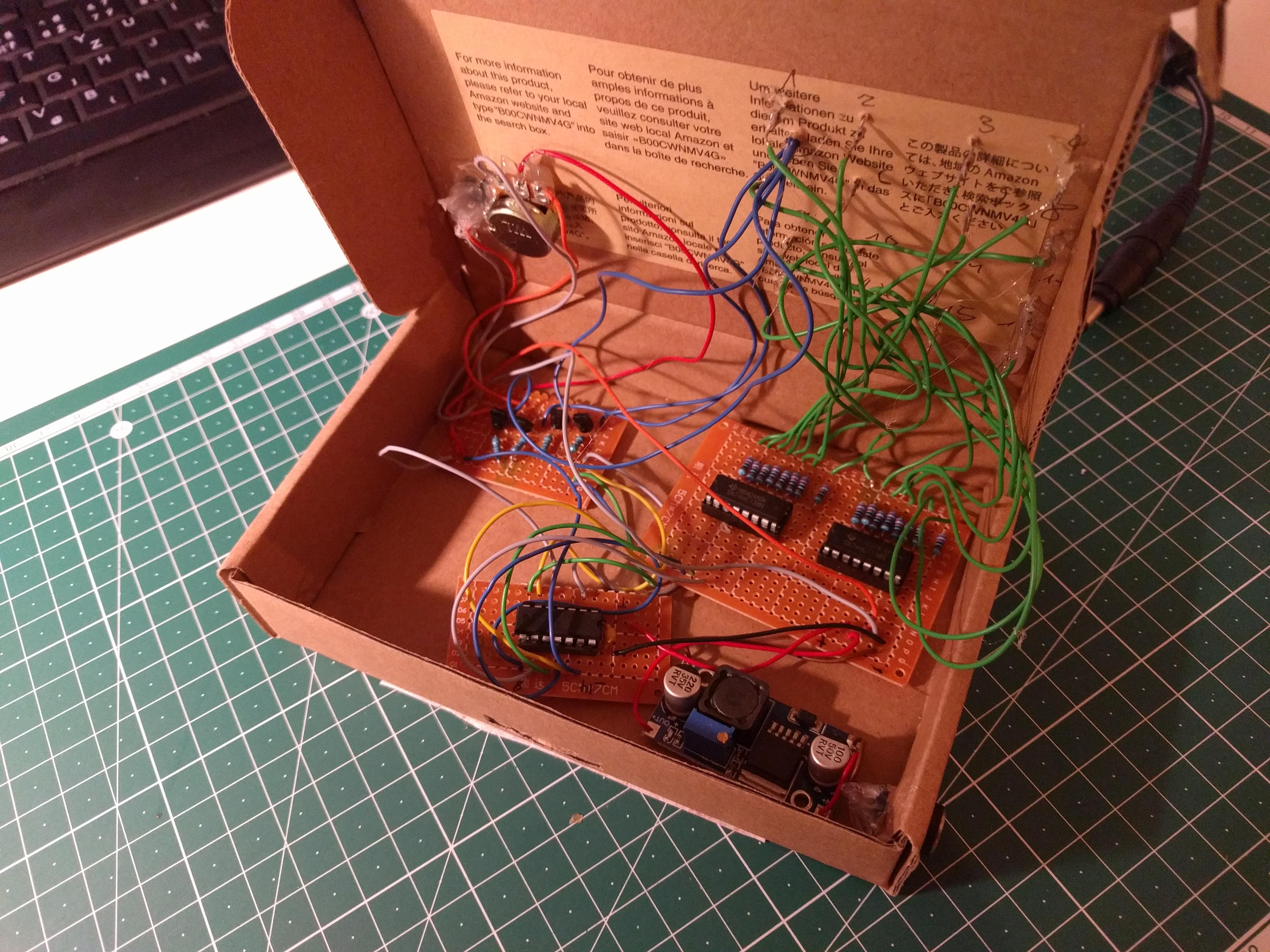
How is my LED cube made
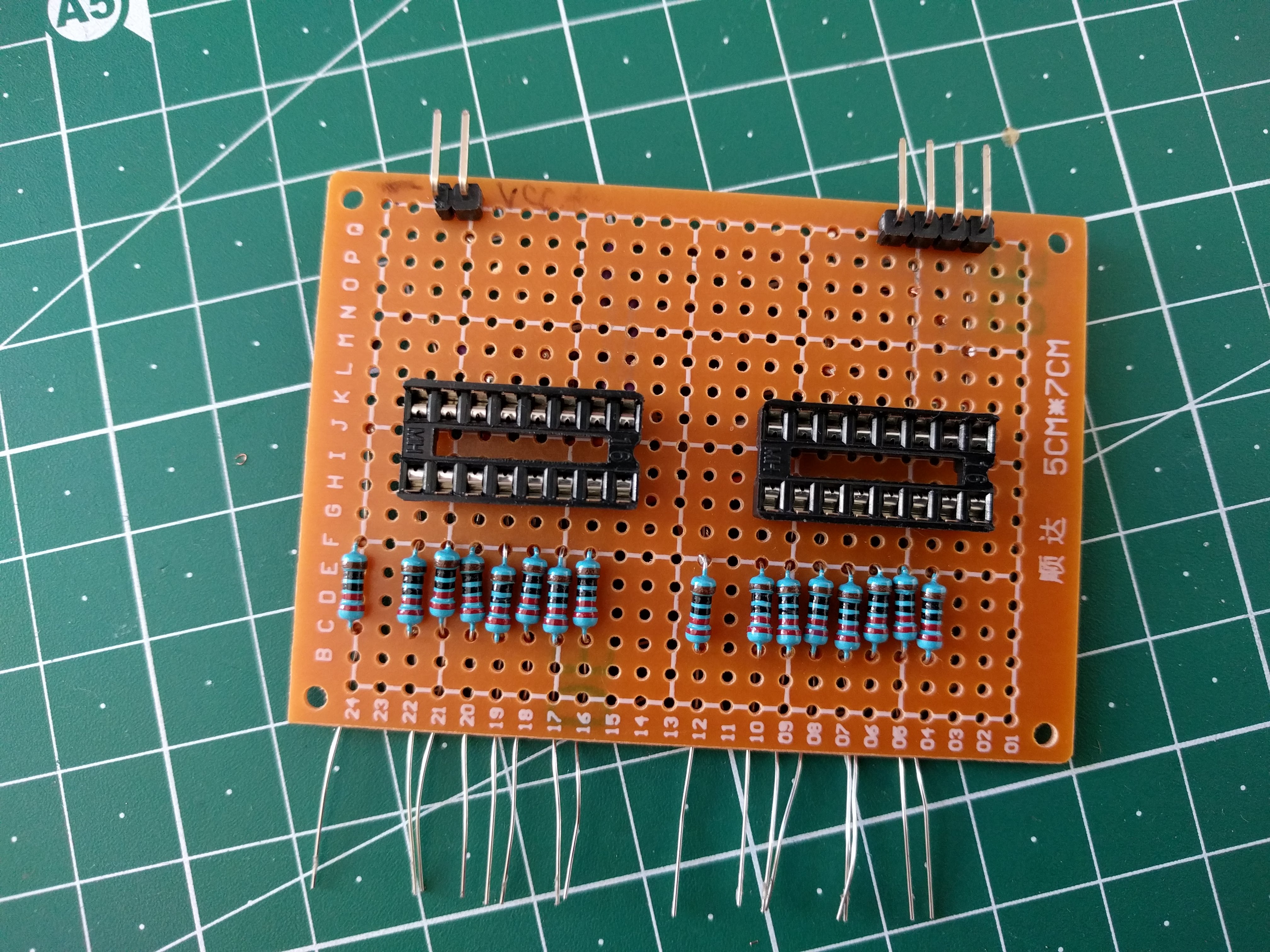
I didn’t really want to buy any specialized components for this project, so I forced myself to use ICs I had at home. I also didn’t want to waste one whole Arduino board on a silly blinking thing, so I decided to drive it by a cheap and small ATtiny84.
There are more solutions to this problem and I decided to use a couple of 3 line to 8 line decoders/demultiplexers (74138). This integrated circuit allows you to select one of 8 outputs with 3 wires, you are basically sending a binary value 0-7 in order to select one output. Here’s a functional table for 74138. The main reason for my decision was simple: I had them at home.
| select | output | |||||||||
|---|---|---|---|---|---|---|---|---|---|---|
| C | B | A | Y0 | Y1 | Y2 | Y3 | Y4 | Y5 | Y6 | Y7 |
| L | L | L | L | H | H | H | H | H | H | H |
| L | L | H | H | L | H | H | H | H | H | H |
| L | H | L | H | H | L | H | H | H | H | H |
| L | H | H | H | H | H | L | H | H | H | H |
| H | L | L | H | H | H | H | L | H | H | H |
| H | L | H | H | H | H | H | H | L | H | H |
| H | H | L | H | H | H | H | H | H | L | H |
| H | H | H | H | H | H | H | H | H | H | L |
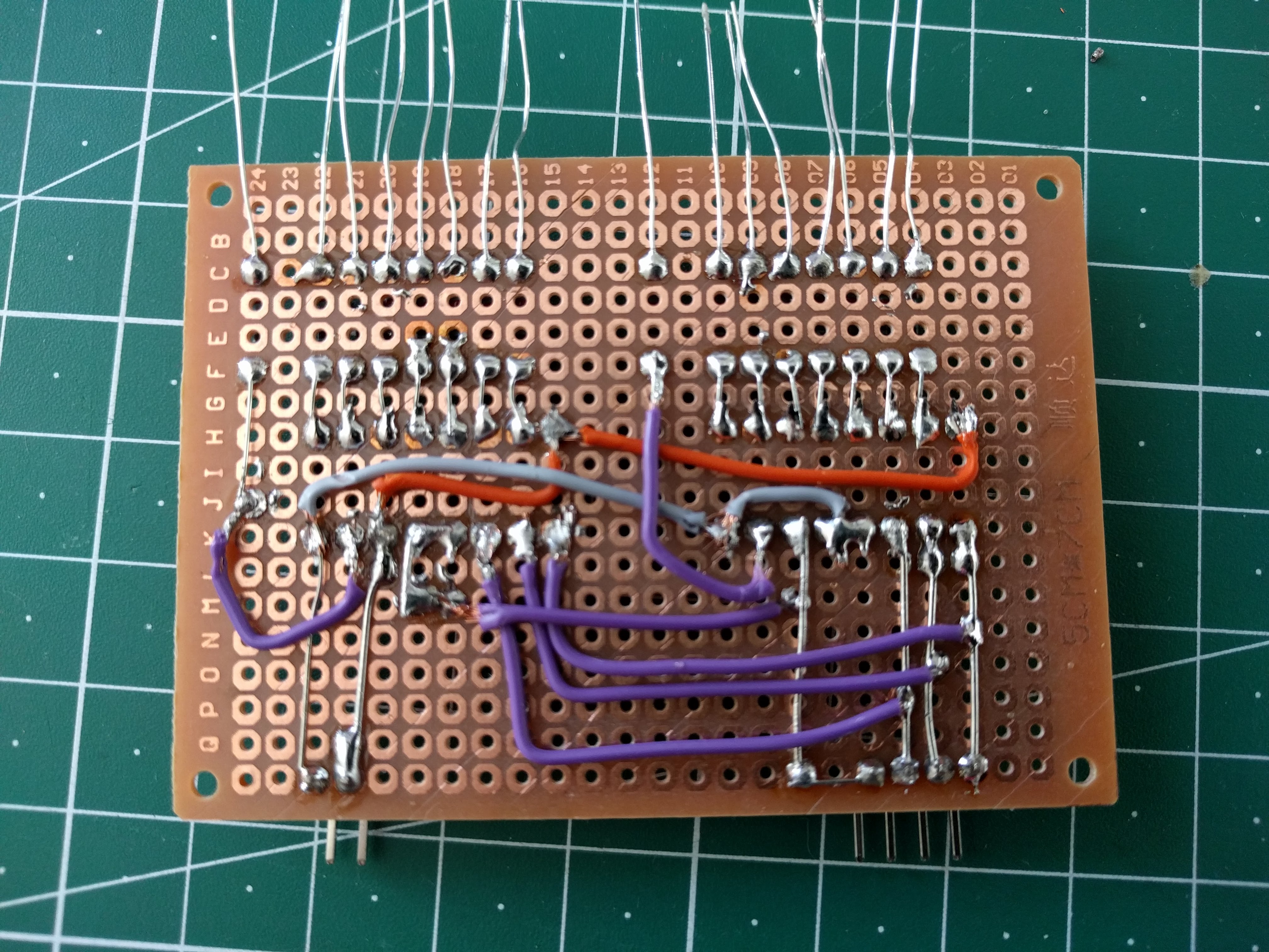
There are another 3 inputs, not included in the table, which allows to select (or enable) the IC. They allow for easy chaining of such ICs. My LED cube has 16 columns, so I needed two pieces of 74138 and that means one additional line for chip selection. So there are 4 pins required for a column selection and therefore 8 pins for the whole cube. Neat. 74138 use LOW signal for selected output. That means that all signals are normally HIGH and only the selected one is LOW. That’s why I had to create columns with a common cathode and not common anode (most of the tutorials online will use common anode for columns).
Although there’s always only one diode turned on and thus a current flowing through ATtiny84 is limited, I still decided to use transistors to power levels. This wasn’t necessary but I felt I would do it just for fun. You can find details in a schematic.
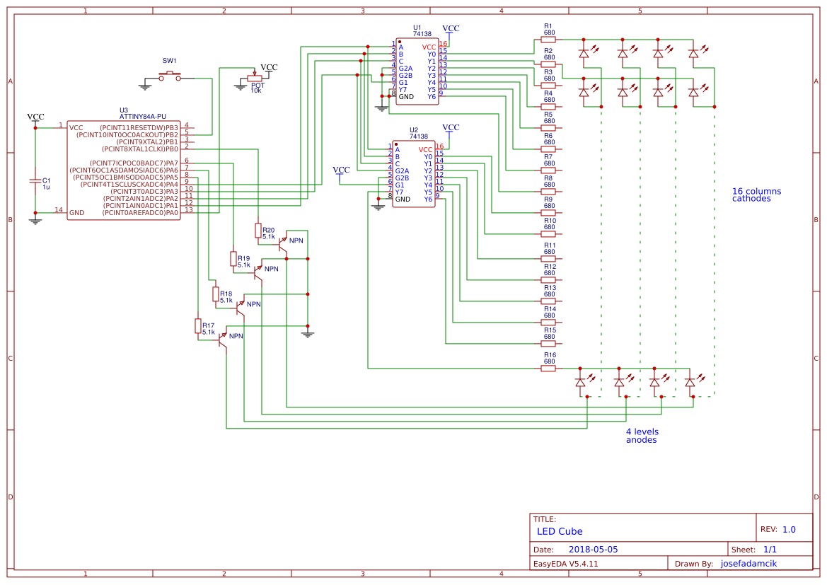
Schematic is also available at EasyEDA.
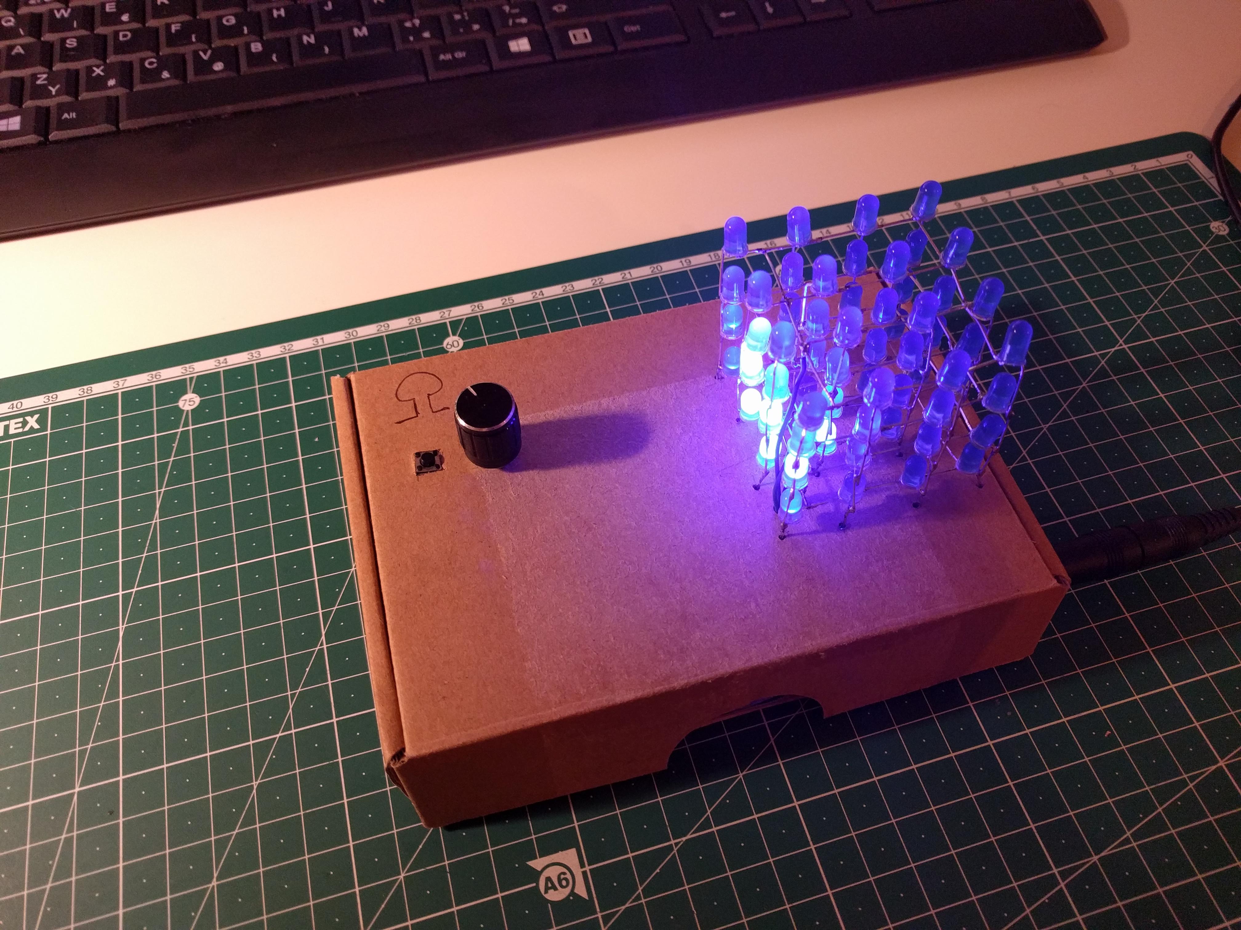
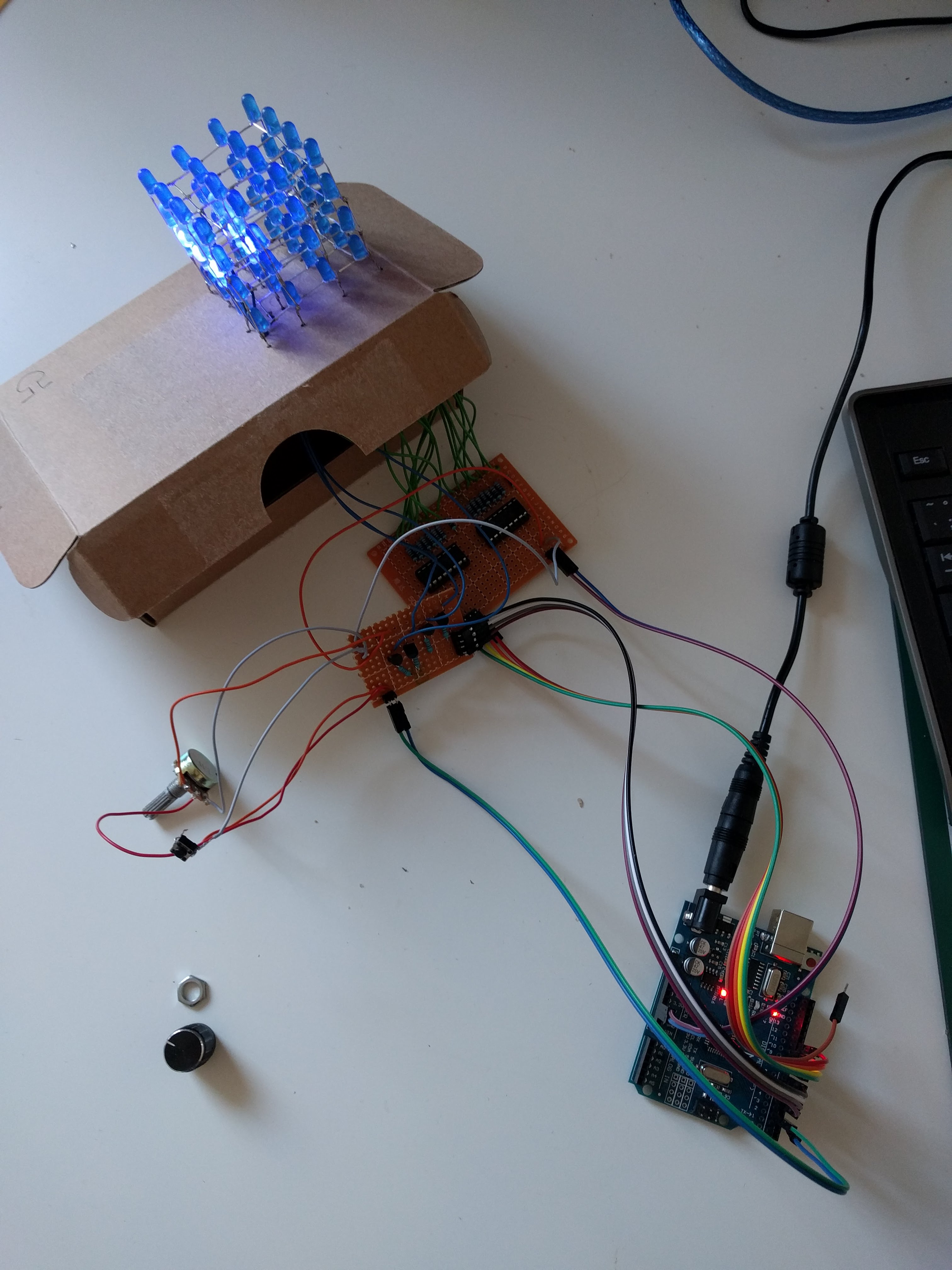
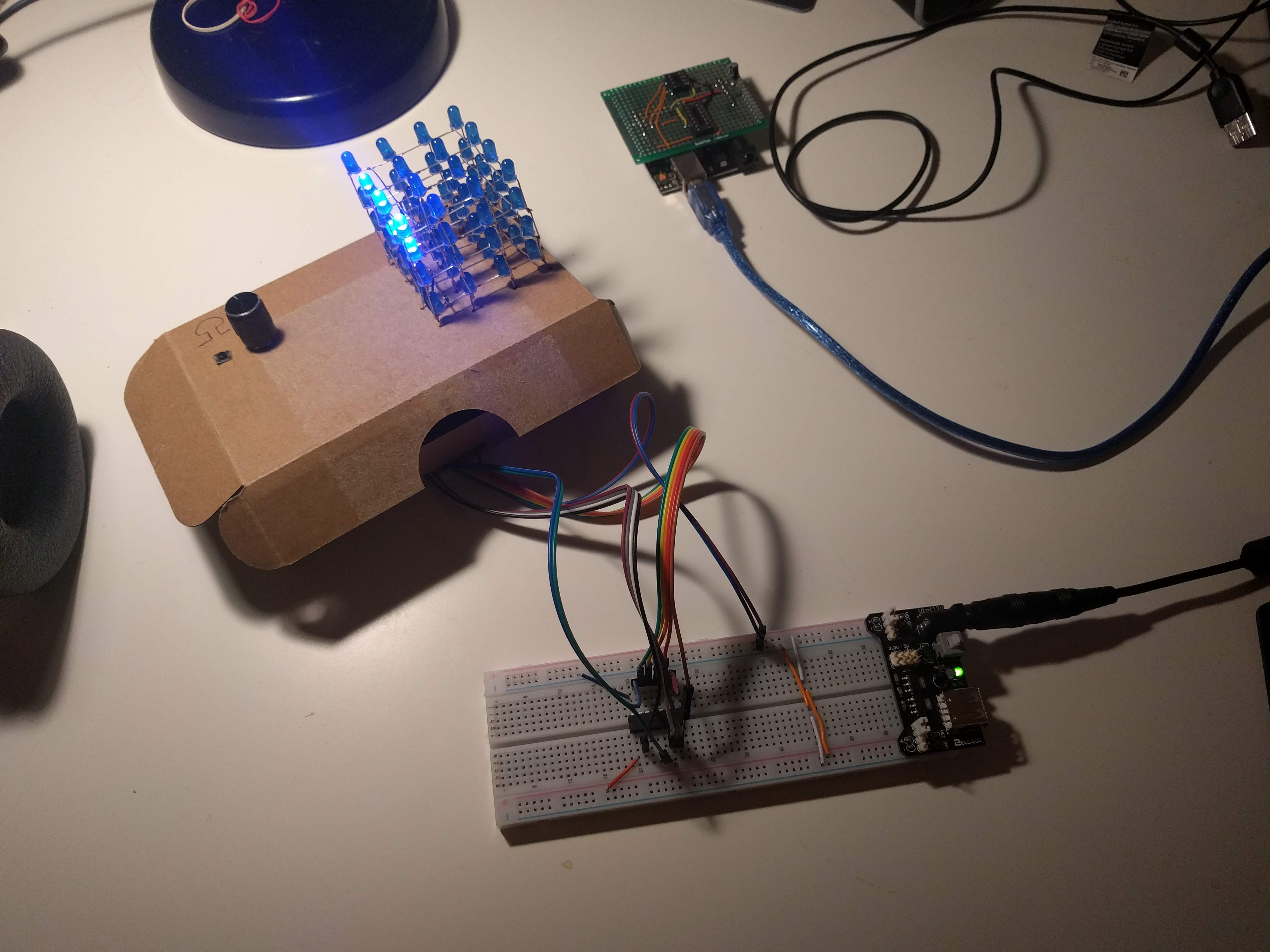
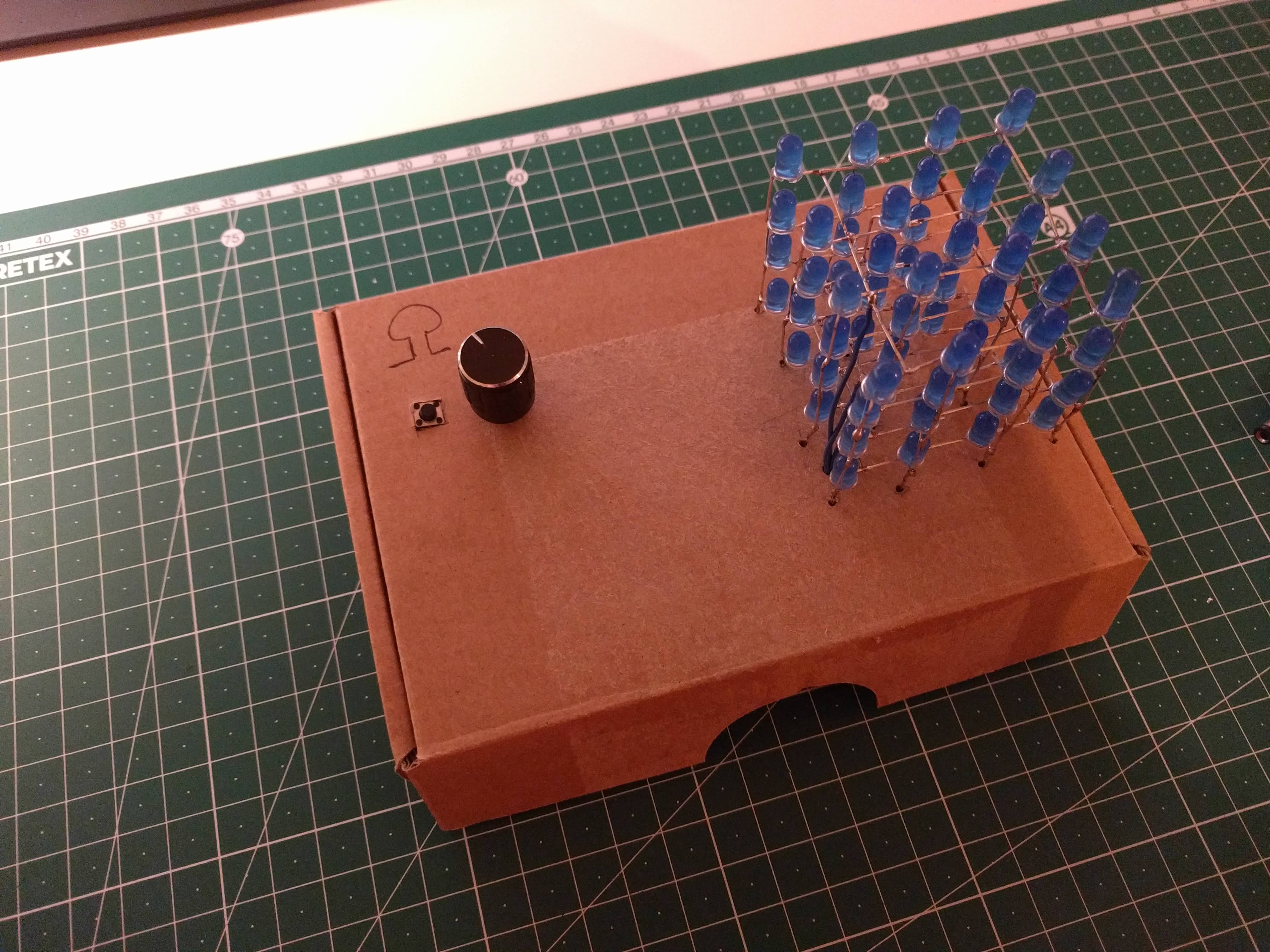
Final build
The cube has three modes: snake, cycling levels and random. A button toggles between modes and a potentiometer controls speed.
Here’s a gallery and a also a video on youtube.
Source code
The code uses Arduino platform. But I moved from Arduino IDE to VisualStudioCode with PlatformIO. Source code is ugly, but it works. I finished the LED cube maybe 2 months ago and quality of code in new projects is going to be better. I am in progress of relearning C++, because I haven’t used it since my studies.
Bill of materials
| pcs | Name + datasheet |
|---|---|
| 1 | ATtiny84 |
| 2 | 74xx138 |
| 64 | 5mm LED diode |
| - | wires |
| - | perfboard |
| 1 | button |
| 1 | potentiometer (10kΩ) |
| 4 | NPN Transistor |
| 16 | resistor 680Ω |
| 4 | resistor 5k1Ω |
| 1 | ceramic capacitor 0.1µF |
| 1 | LM2596 DC to DC buck converter board |
| 1 | DC Barrel Power female connector |
Future?
I might write another mode - game of life or something similar for the LED cube, but otherwise I consider this project to be finished.
I have more work-in-progress projects. The main reason I wanted to wrap-up the LED cube project is, that I am actually finishing another blinking project I would like to report about.