Would you believe this was my first project with ESP32? So far I had some experience only with ESP8266. I must admit I fell in love with ESP32 and I am never going back.
Note: I had this article in my draft folder for several months and forgot about it. So I am giving it just a quick polish and publishing it now.
This article is Part 2 in a 2-Part Series.
- Part 1 -Self-balancing stories, EP 1: How to not start a project made from parts I already have
- Part 2 -Self-balancing stories, EP 2: Developing first firmware
Firmware
This was my first project with ESP32, so far I have only had an experience with ESP8266. I still decided to use Arduino Core for ESP32 even though I was tempted to use the ESP-IDF SDK from Espressif directly (AFAIK Arduino Core for ESP32 just wraps around it). I started writing firmware in VS Code + Platform IO. I cannot use the original Arduino editor since it is.. well, painful for me to use1.
The minimal firmware for self-balancing robot have to:
- be able to get data from IMU (Inertial measurement unit) and compute the lean angle of the robot,
- control the motor (or more precisely the motor driver),
- use that value to compute desired motor speed which would help to stabilise the robot.
But there is more it could do:
- WiFi support and OTA (over the air) updates of firmware
- Bluetooth support and some ability to control and debug the robot remotely.
- Use a waffle iron and bake waffles.
1) IMU - MPU6050
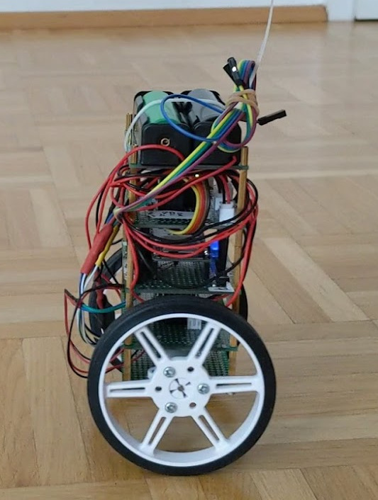
I have a used very common IMU breakout module with MPU6050 which is a six-axis IMU that contains a gyroscope (3-axis) and an accelerometer (3-axis). It uses I2C for communication.
If you check some articles explaining how to use MPU6050, they usually use a combination of values (using a complementary filter) from both sensors in to get a nice and stable estimation of the inclination of the robot.
But there’s a better way since MPU6050 contains DMP (Digital Motion Processor) which can do such computation for you on the chip and provide already filtered values. Sadly it’s not something that would be easy to use. My knowledge of details is limited but it seems like some undocumented feature and requires you to upload some kind of firmware to DMP. It’s most likely designed to be used only with some kind of SDK from the manufacturer.
Thankfully there’s an amazing I2C Device Library that contains Arduino support for many I2C devices including MPU6050 and this support does include DMP. Again, people usually use the library without DMP just to read the raw values. But there’s an example of how to use DMP and the support is included in the library.
The only problem is that ESP32 is not Arduino. I was using Arduino core for ESP32 which mimics Arduino APIs and to a certain level allows usage of Arduino libraries. But the libraries must be either platform-independent enough to compile and work on ESP32 or support ESP32 in the critical parts.
i2cdevlib[[ ]]doesn’t support ESF32 out of the box (certainly not for MPU6050 with DMP). But it was surprisingly easy to make it work. I even created a pull request to the original project but the project doesn’t seem to be actively maintained. There was some communication with a contributor, but it didn’t lead to merging. Nevertheless, I was able to use the library.
2) Control the motor
In order to control a DC motor, or more precisely the H-Bridge motor driver, we need to apply a PWM signal to one of 2 inputs for each motor. One of the inputs is for forward movement the second for reverse. When the duty cycle of the PWM signal is adjusted, the power given to the motor changes proportionally.
A nice hidden Gem of ESP32 is that there’s HW-level support for control of motors through PWM which helps you to generate and control the PWM signals for motors but has also support for failure detection and sensing.
Using MPCWM was quite trivial but I had to dive into the documentation for ESP-IDF. This is one of the things that made me think I could consider getting rid of Arduino core and try to use it directly.
I am not going to explain the details. You can check the current implementation in my Github (look for motor.cpp) and documentation.
3) Drive the motor based on the tilt
Even though there are other options, the most common approach is to use PID (proportional–integral–derivative) controller. There’s a lot one could learn about PID controllers and about system control theory in general. Like many hobbyists, I chose the naive “let’s try it like others and hope it works” approach. I might learn a bit more about the math behind it in the future.
I don’t want to dive into an explanation of details about PID controllers. There is plenty of resource around the internet, for example in this tutorial.
Let me just say that it’s a system that takes an error in some value as an input and spits another value for you. Error, in my case, is the difference between the desired angle of inclination and the measured value. The output value is “speed” for the motor - the duty cycle for the PWM signal in the simplest case. The PID controller has 3 parameters that correspond to the 3 letters of PID (proportional, integral, derivative) and they are often called “gains”. Each of them controls how much one of the aspects considered by the PID controller affects the output.
- The proportional part just uses the error value and ignores time or history. - The integral part integrates error over time.
- The derivative part takes into account the size of the change in error from the last measurement in proportion to the time

Those 3 parameters have to be found experimentally. Of course, system control theory explores how to compute them. But let’s be a proper tinkerer and just wing it.
4) Bluetooth control
The ESP32 used on my controller board supports both Wi-Fi and Bluetooth. WiFi is cool for having an option to update firmware without the need to connect the robot to the computer physically. And Bluetooth is perfect for some remote-control implementation.
Eventually, I would like to have the possibility to drive the robot remotely. But for start, It would be very handy to have the ability to fine-tune parameters for the PID controller and display some debugging information.
It would be possible to make a custom Android app (in the end, I develop Android apps for a living) and some simple communication over Bluetooth. And I might eventually do that. But for starters, I wanted to save time and allow myself to focus on hardware and firmware, rather than doing things I know well - UI for some mobile app, for example.
Thankfully, I have found a neat project called RemoteXY. The website has a simple but capable WYSIWYG editor where you can create a UI for your app. You can pick several UI elements, some act as inputs, some as outputs and some utility ones, like labels or pages.
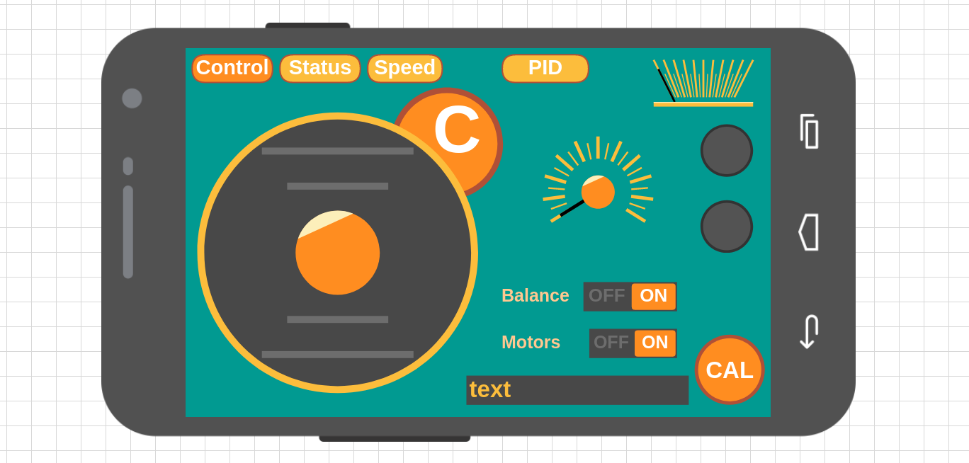
When you are happy with your design the website generates a bunch of code with data for UI configuration and a structure that encapsulates all the input and output values. The next steps are to include this file together with RemoteXY library in your project, install Android APP and go. It’s a very nice experience. The free version of the app is somehow limited but I was so happy with the product I bought the paid version quite quickly. It’s a one-time payment and under 10 Euro - very affordable.
ESP32, Bluetooth and firmware size.
I did run into an interesting issue here and I think it’s worth mentioning. As soon as I started to use Bluetooth in my project the size of my firmware grew significantly. When I had both Bluetooth and WiFi enabled the SDK failed to upload the firmware to my device since it was too big.
ESP32 (at least the model I have) has 4MB of flash memory. Not all of that is used for your firmware. This memory is partitioned into several sections which can play various roles. There’s room for the firmware, room for “EEPROM”, partition you can use to save files (using SPIFFS file system). If you wish to use over-the-air updates you need 2 partitions for the firmware - one is “active” and the other one is used for the new version of the firmware. Once the new version is downloaded, the chip can reboot and switch the active partition.
What I had to do was to change the allocated sizes (I sacrificed SPIFFS partition) to different partitions so both Bluetooth and WiFi support could fit.
5) Reading the speed from encoders
Last but not least I wanted to be able to read the real speed from encoders attached to the motors.
There is even support for this in the ESP32 MPCWM modules so I experimented with that a bit.
Another option is to use the pulse counter peripheral in ESP32 which is very easy to use but sadly doesn’t allow to determine direction of the motor. I was using this approach for quite some time since at the beginning I wasn’t trying to incorporate the speed in the PID loop and used it just for reporting.
But does it work?
Firmware is boring isn’t it? No pictures or videos. The next part should be more fun. There might be even a video!
-
With all the respect to the authors of Arduino IDE and its purpose, I am not able to work with an editor so basic since I am used to working with a professional IDE. ↩
This article is Part 2 in a 2-Part Series.
- Part 1 -Self-balancing stories, EP 1: How to not start a project made from parts I already have
- Part 2 -Self-balancing stories, EP 2: Developing first firmware