It was early pandemic when my employer switched to the work-from-home mode and I realized I have a bit more free time since my commute times dropped to zero. Apart from keyboard stuff, I had no nice project in progress that wouldn’t involve waiting for PCB manufacturing or parts. So, what could I build from things I have at home? What about those 2 cheap geared DC motors, those 2 wheels, some micro, IMU unit. Hmm. I see a 2-wheeled self-balancing robot here. I always wanted to build one and learn how they work.
This article is Part 1 in a 2-Part Series.
- Part 1 -Self-balancing stories, EP 1: How to not start a project made from parts I already have
- Part 2 -Self-balancing stories, EP 2: Developing first firmware
Gathering parts
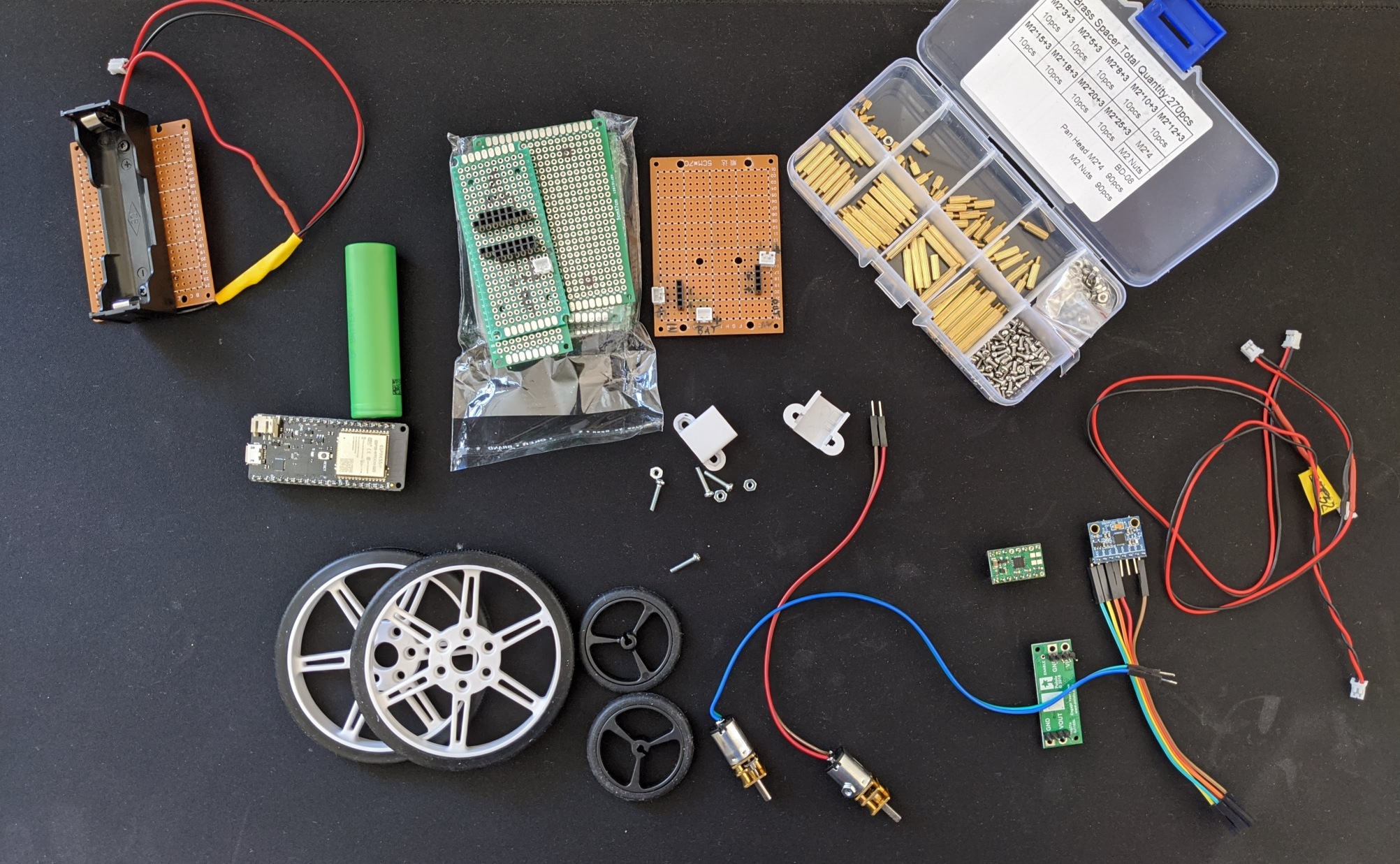
The idea sounded great. I had all the electronics, but what about the body of the robot? I had no 3D printer, not even a nice workshop, no materials like plywood or acrylic sheets. So the only solution apart from cardboard seemed to be to use prototyping PCB perfboards and some standoffs I had lying around.
And that was when the idea started to fall apart. My stock of M2 spacers was quite weak. I had plenty of nylon M3 but those are too big for mounting holes in the perfboards. Also, I didn’t have enough perfboards of the same size to make the whole robot. I tried to utilize some super cheap one-sided ones and tried to drill holes for M3 spacers. I failed horribly destroying most of my materials. I also didn’t have any bracket to fix the motors to perfboards. And the wheels - oh my god, they were just too tiny and motor shaft too big for them.
I tried at least to prototype the electronic. Let’s use a LIon cell here, a step-up voltage converter to 6V (that’s what the motors are rated for). ESP32 on a dev board as a micro-controller, L298N h-bridge dual motor driver. Everything I had at my storage, just waiting to be used.
Well, the step-up was terrible since it wasn’t really possible to set a fixed output voltage. The regulating potentiometer needed to be adjusted when the load was connected or changed. I ended up maxing it out to have the desired 6V on the h-bridge during load.
The L298N wasn’t any win either. It has quite a big voltage drop so my motors weren’t getting their 6V, but rather something like 4.5V.
All this made me quite sad and disappointed at first. Until I gave up my “use just parts at home” idea and filled one virtual shopping basket with a couple of robot wheels, brackets for attaching them to the frame, better step-up board (fixed voltage 6V), better motor driver. And yeah, let’s also take a bunch of properly sized protoboards and I would also take this M2 spacer assortment, please. Everything ordered from Germany to minimize shipping times.
Version 1, construction
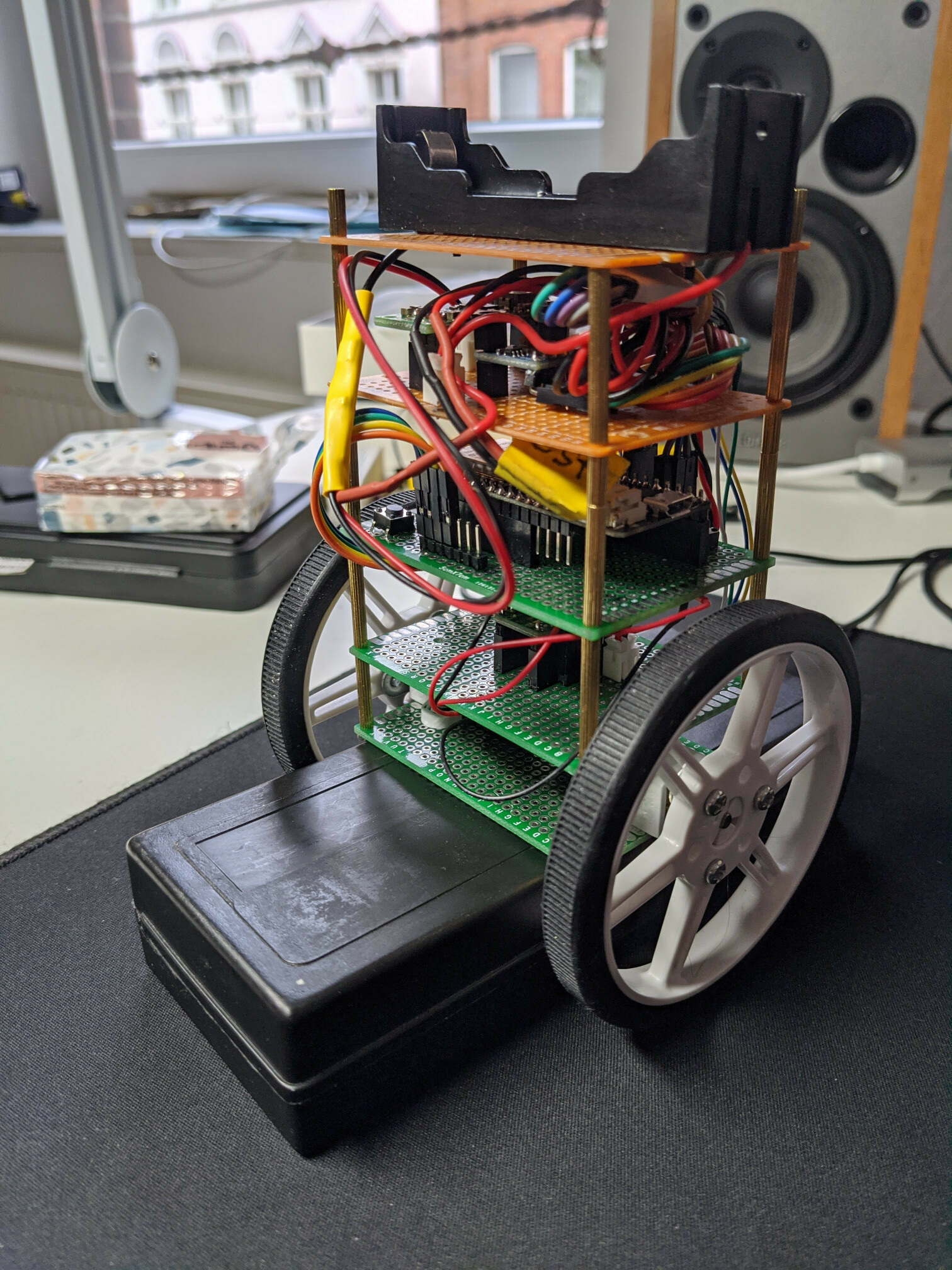
Now I could finally start constructing my robot!
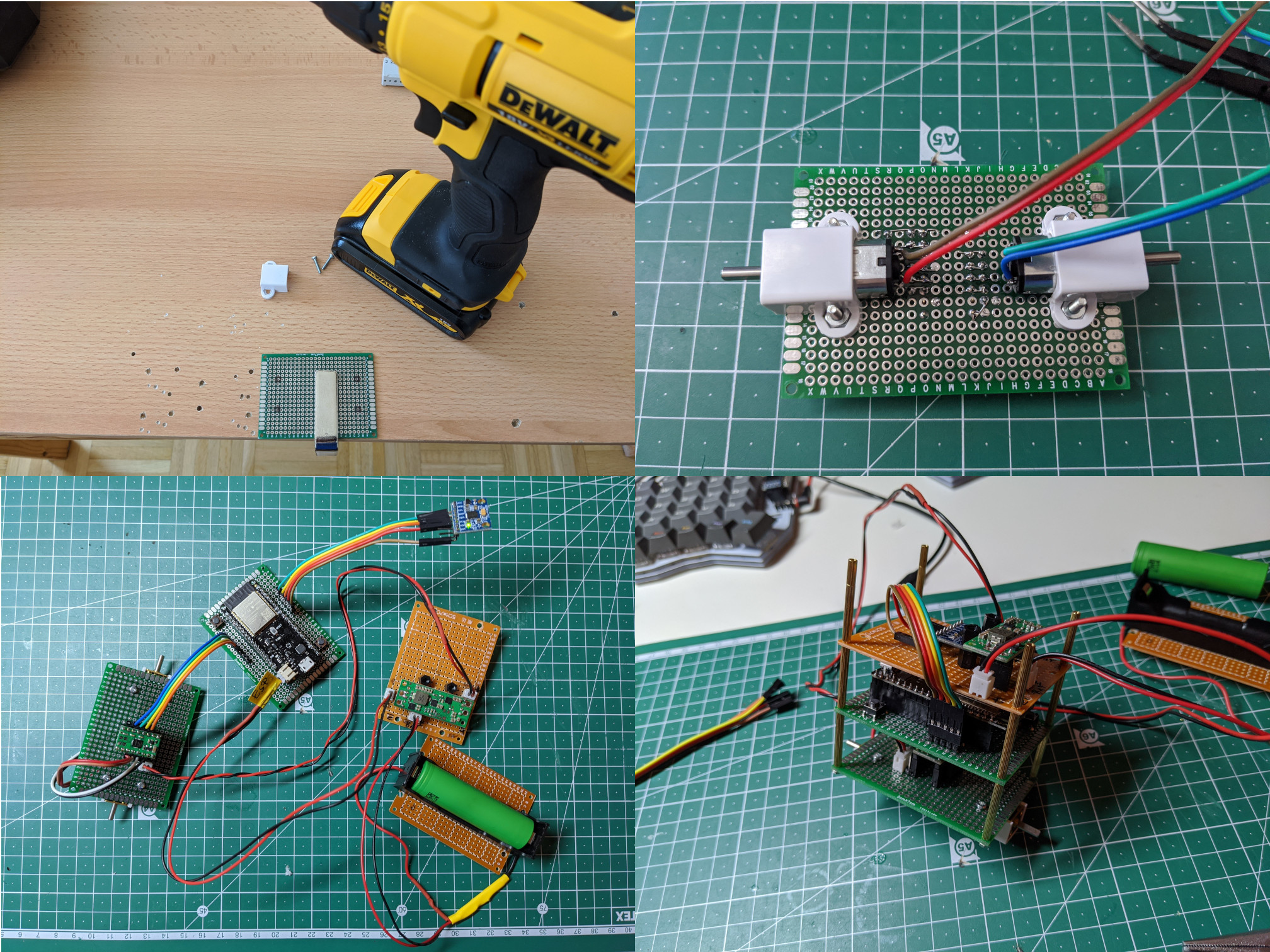
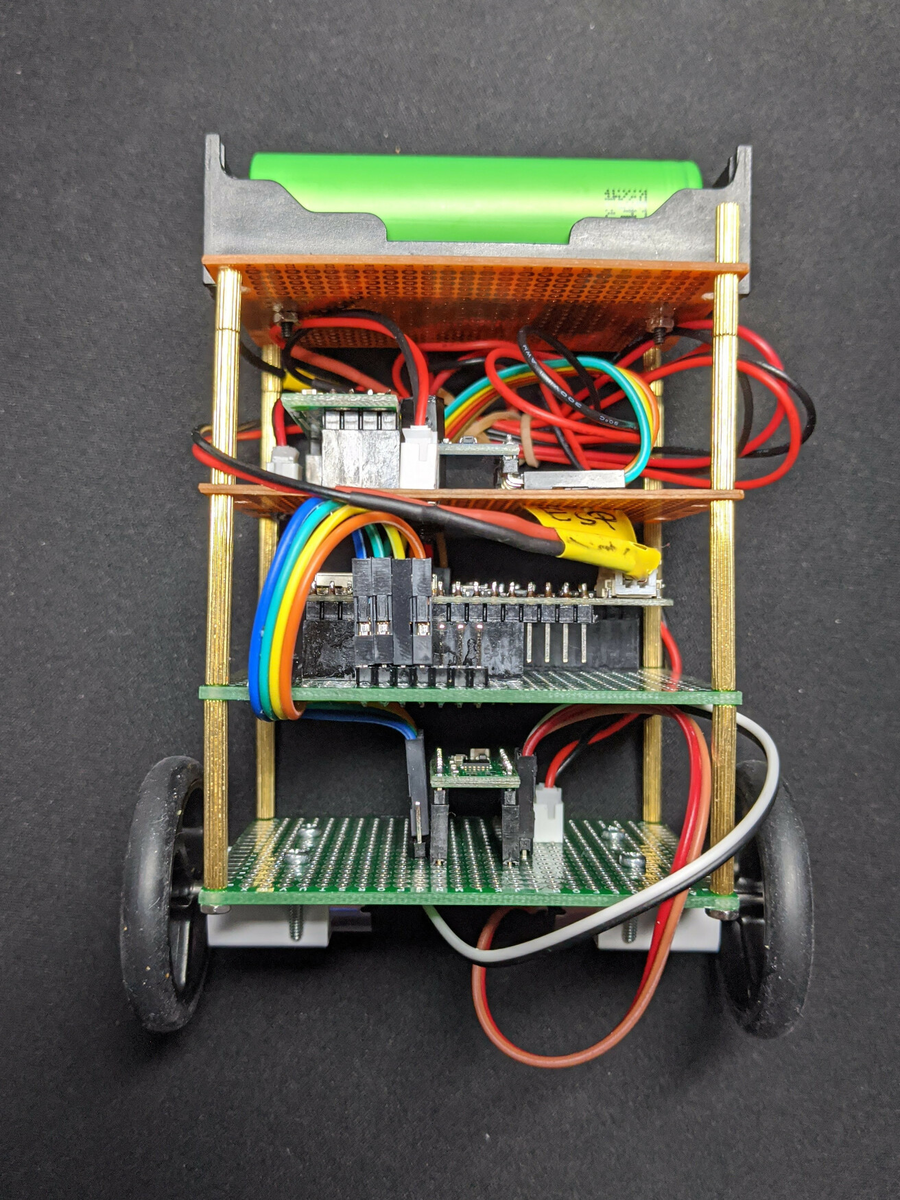
You can see overall it’s quite simple. One board contains motors attached using brackets at the bottom and DRV8833 dual h-bridge motor driver
The second level is dedicated to the controller board. I believe it’s one of the early versions of Wemos Lolin32 or a clone. I bought it on Aliexpress quite some time ago. It uses the ESP32-WROOM-32D module with Bluetooth and WiFi support and 4 MB of flash memory. I think it’s possible is actually the first silicon version which was a bit buggy but shouldn’t be that big deal for my purposes.
The third level contains the 6V step-up and MPU6050 breakout board.
The top level has a holder for one LiOn cell. This one cell powers directly (through a protection circuit) the controller board (which has an onboard regulator) and the step-up regulator for motors - both are technically in parallel with the battery. Yes, that does sound like I am asking for power issues and they will come later, don’t worry.
This is how the first version looked with the smaller couple of wheels (40 mm). I bought also 80 mm ones which I ended up using and you can see them on the title image.
You can see it’s lying on its back, partly because no firmware was written at the time the picture was taken and partly… Well, let’s leave that for later.
Problems and another order
I did spend some time writing firmware since there’s quite a lot to do there. But I’ll leave the details for the next article. Once I had some basic version ready and started testing the robot I very quickly realized that my motors are too weak. Like crazy weak. Guess what I had to do? I had to buy new ones.
The thing is it’s not really easy to pick a motor for such a robot. I wanted to stay with this size/format of the motor which is usually called “micro gear motor”.
But still, there are several questions:
- Which voltage? they are made in 3V, 5V, 6V but 12V versions.
- Which Gear ratio?
- Which speed RPM would be the best?
- Which stall torque is enough? And what “stall torque” actually is?
As you may guess those things are connected.
Higher voltage would usually mean a more powerful motor. And more powerful means either higher speed and/or higher torque. Gear ratio allows you to exchange speed for torque. Apart from rated voltage the power of a motor is also affected by its construction. For example, Pololu offers for every voltage rating several types: LP (low power), MP (medium power) and HP(high power). The more powerful a motor is the more current it’s going to consume.
The motor needs enough torque to move the robot’s body into an upright position so the amount of torque required depends on the construction but also on the starting angle. Balancing in the position would require much less than making the robot to stand up when it is lying on the ground. You could actually compute the torque needed if you knew parameters of the body that’s going to be moved.
The speed you see in the datasheet (or in the table linked above) is the speed of the motor without any load. The more load it needs to carry (that’s our torque, actually!) the slower it moves. Stall torque is the torque the motor reaches when its speed reaches zero. We could say that motor cannot handle higher torque and we should stay below the value. Each motor has also “stall current” which is the current consumed in the stall state and you need to keep it in mind when picking your motor driver and setting up the power (step up, protection circuit and battery).
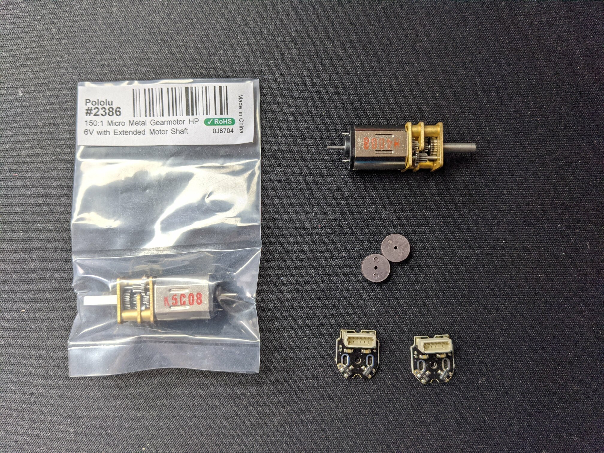
I did plenty of research but in the end, I still picked motors mostly by guessing and I am still not sure if I made a good decision or not. My pick was 6V HP variant, 150:1 Gear ratio. This one is rated for 210 RPM when not under load (consuming 70 mA) and stall torque 2.4 kg.cm (consuming 1.6 A when stalled).
Since I already knew that it might be handy to measure the real speed of the motor I chose the version with an extended motor shaft which would allow me to connect magnetic encoders and I also ordered few of them.
Next steps
This story begun with a small project made from parts I had at home and but I quickly ended up buying quite a lot of new components. Only the MPU6050 breakout, ESP32 controller board, battery and holder (and of course, jumper wires, cables etc.) are from my storage. I think I have spent 80-90 Euro for the rest (all shipped from Germany).
Thankfully, the motors seem to be powerful enough to balance the robot but I run into power issues. My ESP32 was restarting due to brownout quite often and it was impossible to actually balance the robot.
But let me take a break from the hardware side. In the next article, I am going to focus on the firmware and after that, I’ll return back to HW.
This article is Part 1 in a 2-Part Series.
- Part 1 -Self-balancing stories, EP 1: How to not start a project made from parts I already have
- Part 2 -Self-balancing stories, EP 2: Developing first firmware