This project an example of how one project can lead to another. I have recently revisited an old hobby of mine - building and painting scale models. Even though the resulting model is a work of a beginner with many flaws I still wanted to have some nice pictures of the result. And it wasn’t for the first time it crossed my mind that it would be nice to have an automatic rotating turntable so I could easily make a 360 video of something I made.
The plan
You can o buy those (just search for “photography turntable” anywhere). The main use is product photography which is not really about taking a video but rather about taking pictures from many angles so you can create a 360-degree view for an e-shop. Such a turntable can be connected to a camera and triggers the shutter after rotating for a given angle. You can imagine those can have plenty of features to support similar use cases.
My use case is much simpler. I want a slow smooth rotation of an object so I can put my cell phone on a tripod and capture a short video. The controls I need are an on-off switch and something to adjust speed and direction.
Electronics
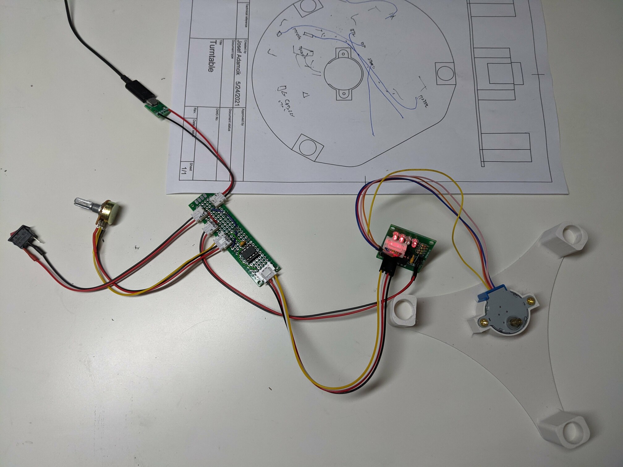
All the electronic parts I already had laying around:
- 5V stepper motor (28BYJ-48) with a corresponding driver board
- On/Off switch
- Potentiometer
- Arduino board (later replaced with a bare Attiny85)
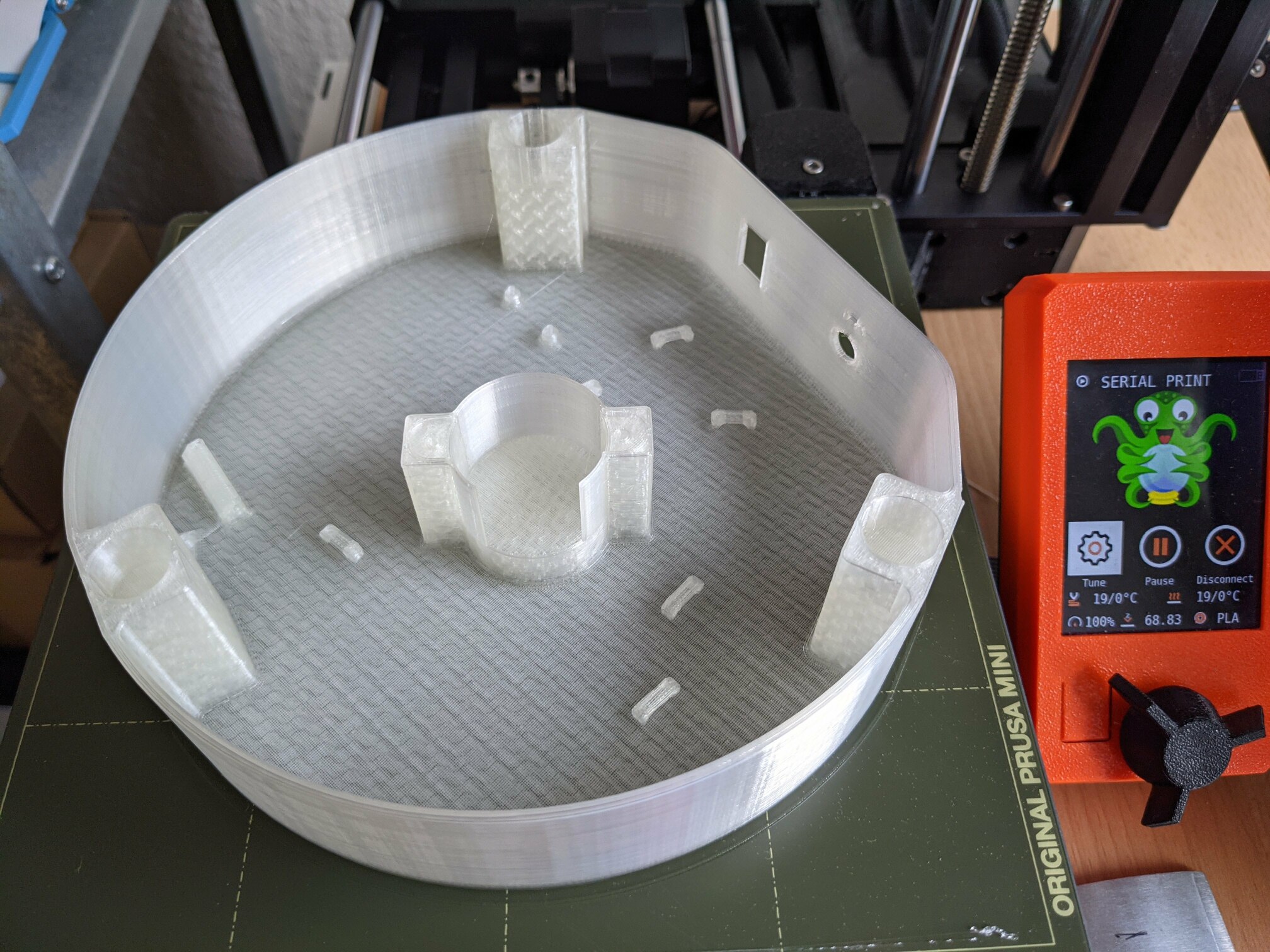
3D printed design
The only important question regarding the design that needs an answer is how to mount the rotating part (table) to the base so it can freely rotate and the weight is not fully suspended only on the motor shaft. I did some research on Thingiverse and stumbled upon a fully 3D printed manual turntable by Brian Brocken I quite liked.
My first design was an attempt to use a similar fake bearing to support the table and smooth the rotation.
Even though I went through 2 or 3 iterations I wasn’t happy with the result. The movement wasn’t smooth enough. Interestingly one direction was more troublesome than the other. Also, slower speed was causing more stuttering.
Brian Brocken who designed the original design I took the inspiration from also designed a real 3D printed bearing. So my next attempt was to recreate such a 3D printed bearing instead of the fake one.
This was much harder than I anticipated. I had huge trouble with tolerances. Even though I started with a smaller bearing to speed up prints and figure things out I still had to iterate multiple times over the whole big bearing. I must admit that this design was stupid from the beginning. The worst part is that the performance was even worse than with the first design.
Again it’s not apparent on the video since it captures the best output I was able to get. In general, it was less reliable and more stuttery than the first design. The baring was even able to get completely stuck since the “balls” were able to flip 90 degrees from their proper rolling position.
It was a nice exercise of working with Fusion 360, though.
There is one very nice and sophisticated design for this kind of rotary table by Valera Perinski on Thingiverse. I have seen it when I did my original research but found it a bit over-engineered for my purposes. He uses nylon caster rollers in his design. Originally, I wanted to avoid ordering them and took it as an interesting challenge to fully 3D-print the mechanism. But at this point, I was quite tired of the project so I gave up and ordered them from AliExpres.
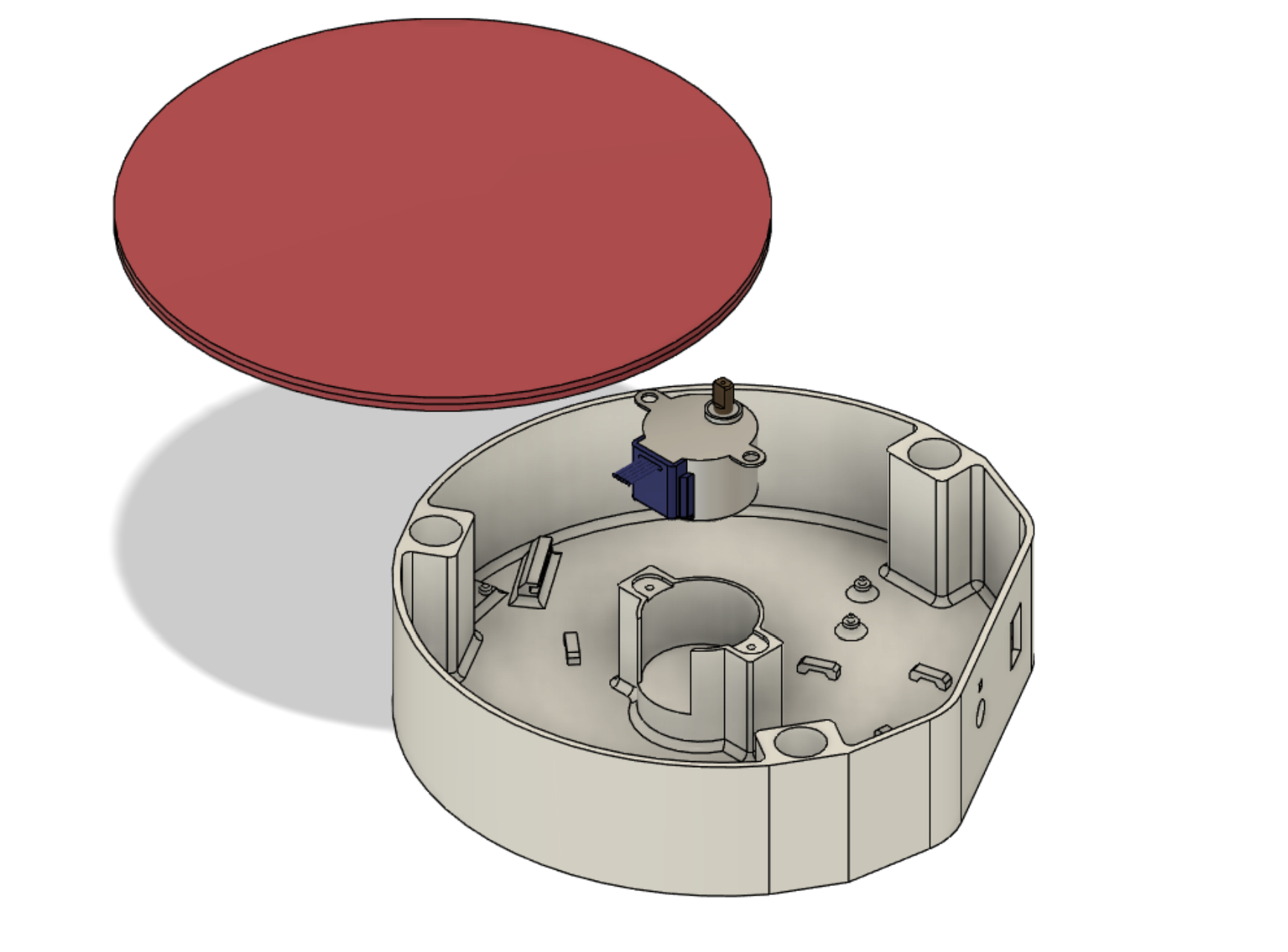
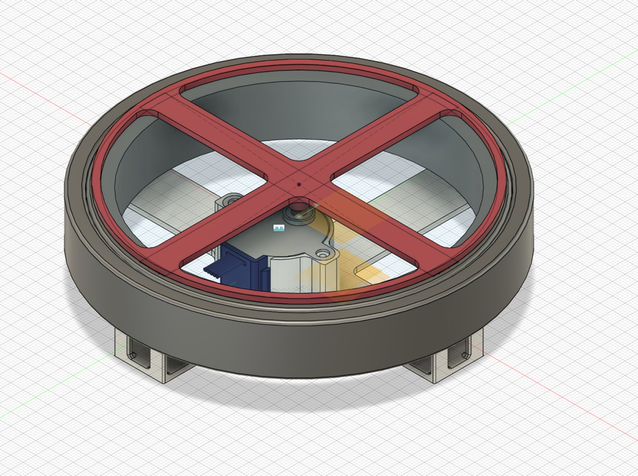
And this leads to the final iteration. 3 caster rollers are used to support the rotating table.
This version did have much better results than the second one but the improvement over the first iteration wasn’t as big as I hoped for. The motion still tends to be less smooth in one of the directions (most likely just a problem with the motor) and some stuttering can be seen here and there. But it is possible to get quite smooth slow rotation. Anyway, I was already quite tired of the project and wanted to wrap it up quickly.
Final design
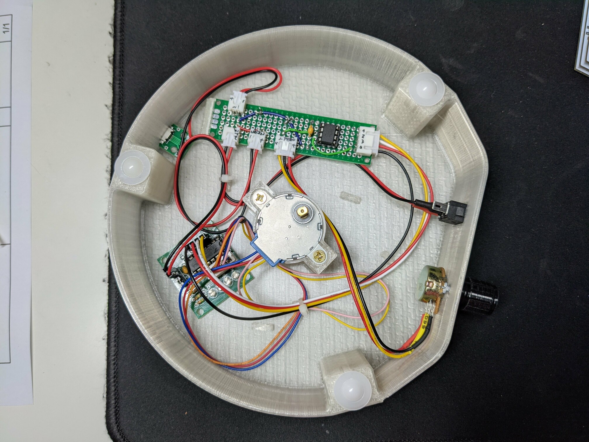
I used some quickly prototyped circuit and an Arduino board for the whole prototyping project. For the final version, I wanted something a bit more permanent. It also doesn’t really make sense to use a whole Arduino board to generate the driving signal. Attiny85 is the perfect microcontroller for this device. Given the simplicity of the project, a perfboard and few connectors are all that was needed.
As you can see above, the prototypes had both the base and the table minimal so I was able to print them quicker and save some filament. The final design should have a proper enclosure.
Originally, I wanted to have some clever way how to mount everything in place. The on/off switch and potentiometer were easy since they are designed to be mounted. I managed to make quite a nice snap in place for the USB connector. But I got bored when I was trying to design a snap-in mount for PCBs. The main PCB (perfboard) has some kind of mount in the design, but I still had to use a bit of hot glue to keep it in place. The motor driver board is hot glued without any attempt to design a snap-in mount.
And here’s the final build in action.
I don’t think the design is interesting enough to be published. I would suggest using or adjusting the design by Valer Perinski directly rather than using mine.
If anyone is hugely interested the STL files are here:
The Fusion 360 design file is a mess so I am not going to publish it. It would be easier to make the design from scratch than to adjust it in the messy file I have.
And the firmware (for Arduino/Attiny85 using Arduino Stepper library) is available here on Github, even though the code is super primitive.
Even though the project required much more effort than I anticipated and I got a bit annoyed by the end, seeing the result is as always very satisfying. I spent quite some time taking videos of rotating things. Here is one of the model that started this.